SPECIFICATION
Section 1—485/R485 Service
Introduction
The 485/R485 is a general-purpose, environmentalized,
high-performance, portable, wide-band oscilloscope which
has a dual-channel vertical amplifier with selectable input
impedance (DC to 350 MHz bandwidth with 50 £2 input
impedance; DC to 250 MHz bandwidth with 1 M£2 input
impedance). The 485 has a 1 ns sweep rate, stable triggering
to bandwidth limits and calibrated X-Y capabilities.
Delayed sweep has calibrated delay time, can be triggered
after delay and can be displayed with the intensified main
sweep in an alternate sweep switching display. Additional
features are X I0, X I00 probe scale factor readout, 8 div
X10 div graticule area, small spot size and high writing rate.
A 20 MHz bandwidth limiter, 1 MHz and 1 kHz fast-rise
calibrator and autofocus are also included. The 50 £2 input
is automatically disconnected from excessive voltages. An
external trigger view feature is also provided. The 485-1 and
485-2 have no external trigger view. The 485-2 has only 50
£2 vertical input impedance.
ELECTRICAL CHARACTERISTICS
Input Coupling Selection
AC; DC; GND (provides zero reference, precharges
coupling capacitor, disconnects 50 £2 load in 50 £2
mode).
Lower —3 dB Point (AC coupling from 50 £2
source)
50 £2 input, 1 kHz or less.
1 M£2 input IX , 10 Hz or less.
Deflection Factor
5 mV/div to 5 V/div in 10 calibrated steps (1-2-5
sequence), accurate within 2%. Uncalibrated, continu
ously variable between steps to at least 12.5 V/div.
Lights at edge of knob skirts indicate correct deflection
factor for IX , 10X and 100X probes.
Gain can be recalibrated at front panel. 1 M£2 BAL is
available at bottom panel to eliminate step attenuator
shift above 10 mV/div, in the 1 M£2 mode.
VER TICAL DEFLECTION SYSTEM
(2 identical channels)
Display Modes
Channel 1; Alternate; Chopped (approximately 1 MHz
rate); Added; X-Y (CH 1 -Y and CH 2 -X ); Channel 2
(+Up or Inverted).
Selectable Input Impedance
50 £2 within 0.5%. VSWR <1.25:1 on 5 mV/div and
10 mV/div, 1.15:1 from 20 mV to 5 V/div to 350 MHz.
1 M£2 within 1% paralleled by approximately 20 pF.
Bandwidth1 and Risetime2 (VARIABLE gain
CALIBRATED3) From 50 £2 Terminated Source
—15°C to +35°C
From 50 £2 terminated source —15°C to +35°C.
50 £2 DC to at least 350 MHz, 1 ns
1 M£2 DC to at least 250 MHz, 1.4 ns
Bandwidth (BW) measured at —3 dB down.
2Risetime calculated from 0.35/BW. From +35°C to +55°C, BW is
300 MHz for 50 ft and 200 MHz for 1 MU.
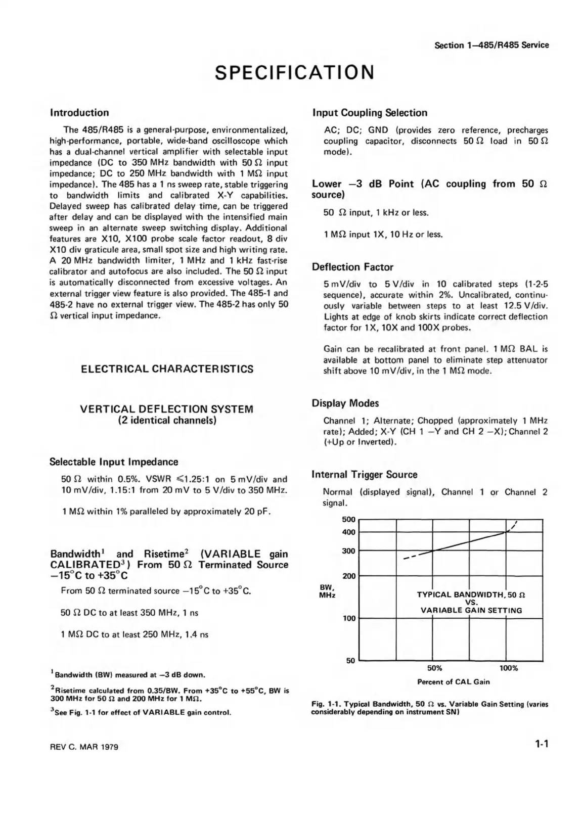
3See Fig. 1-1 for effect of VARIABLE gain control.
Internal Trigger Source
Normal (displayed signal), Channel 1 or Channel 2
signal.
500
400
300
200
BW,
MHz
100
50
Fig. 1-1. Typical Bandwidth, 50 ft vs. Variable Gain Setting (varies
considerably depending on instrument SNI
/
/
TYP
VA
ICAL BAh
V
RIABLE C
DWIDTH.
IS.
AIN SET!
50 ft
ING
50% 100%
Percent of CAL Gain
REV C. MAR 1979
1-1

 Loading...


