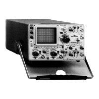
Operating Information—485/R485 Service
A VARIABLE
Control
DLY'D SWEEP
PULL Knob
POSITION (hori
zontal) Control
Rear Panel
TRACE ROTATION
Adjustment
FOCUS and ASTIG
Adjustment
B +GATE
A +GATE
A SWEEP Connector
Provides continuously variable A
sweep rate to approximately 2.5
times the calibrated setting (uncali
brated sweep rate is extended to
1.25 s/div). Push away control
provides calibrated rate in the CAL
IN position.
Provides for advancing the B
(DLY'D) sweep rate ahead of the A
(DELAYING) sweep rate. (When A
rate is 1, 2, or 5 ns/div the concen
tric knobs are locked together, and
only the A sweep is displayed.)
Horizontally positions trace. In
operative in X-Y mode.
Screwdriver adjustment to align
trace with horizontal graticule lines.
Adjustment used to obtain a well
defined display. Requires infre
quent readjustment.
BNC Connector providing a
positive-going rectangular waveform
coincident with B sweep.
BNC connector providing a
positive-going rectangular waveform
coincident with A sweep.
BNC connector provides a sample
of A sawtooth generator signal.
Z AXIS INPUT BNC input connector for intensity
Connector modulation of the CRT display.
PROBE POWER Two 4-pin connectors at the rear of
the instrument provide power suit
able for optional active probes such
as the P6201.
LINE CORD Power cord is a 3-wire, permanently
attached cable, approximately 7.5
feet in length.
LINE VOLTAGE Recessed slide switch selects nomi-
SELECTOR nal operating line range. 115 V (90
to 136 V) or 230 V (180 to 272 V).
OPERATING TIME Elapsed operating time indicator.
5000 hr. scale.
Bottom Side
1 MS2 BAL, Adjustment provides for DC bal-
CH 1 and CH 2 ance of 1 MJ2 Buffer amplifier.
NOTE
Two types o f crt graticules have been used in some
Tektronix oscilloscopes. One graticule has 0% and
100% risetime reference points that are separated by
6 vertical graticule divisions. The other graticule has
the 0% and 100% risetime reference points separated
by 5 vertical divisions. In your manual, illustrations
o f the c rt face or risetime measurement instructions
may not correspond with the graticule markings on
your oscilloscope.
2-4
REV. B, MAR. 1976

 Loading...