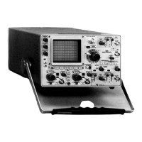
485/R485 Service
TABLE OF CONTENTS
SECTION 1 SPECIFICATION Page
Introduction 1-1
Vertical Deflection System 1-1
Probe Performance 1-3
A and B Triggering 1-3
Horizontal Deflection 1-4
Calibrated Sweep Delay 1-4
X-Y 1-5
CRT 1-5
Calibrator 1-6
Other Characteristics 1-6
Environmental Characteristics 1-6
SECTION 2 OPERATING INSTRUCTIONS
General 2-1
Preliminary Information 2-1
Controls and Connections 2-1
Front Panel 2-1
Rear Panel
2-4
Bottom Side
2-4
SECTION 3 CIRCUIT DESCRIPTION
Introduction 3-1
50 n Attenuator 3-1
1 Megohm Buffer Amplifier 3-1
50 n Overload Protection 3-1
Vertical Preamplifier 3-1
Signal Channel Switch 3-2
Internal Trigger Amplifier 3-2
Main Vertical Amplifier 3-2
Scale Factor Readout 3-3
Vertical Mode Control 3-3
Z Axis 3-3
A Trigger Amplifier 3-3
A EXT Trigger Identify 3-3
A Trigger Generator 3-4
B Trigger Generator 3-4
A and B Sweeps 3-4
Horizontal Amplifier 3-5
Horizontal Control 3-5
Power Inverter/Regulator 3-6
Line Filter 3-6
Line Input Circuit 3-6
Start Network 3-7
I nverter 3-8
Inverter/Regulator 3-8
Inverter Current Limiting Circuit 3-8
Overvoltage Stop Circuit 3-8
Line Stop Circuit and Surge Limiting 3-8
Procedure for Converting the 485 to
DC Operation 3-9
Low Voltage Supplies 3-9
Power Supply Protection Circuit 3-10
Stop Monostable 3-10
Balance Node 3-10
Overcurrent Protection 3-12
Low Line Voltage Protection 3-12
Sampling Period Timer and Over-
Voltage Protection 3-12
CRT Circuit 3-12
Filament Voltage 3-12
High Voltage Supplies 3-12
Anode Supply 3-12
Cathode Supply 3-12
Cathode Regulator 3-12
Grid DC Restorer 3-13
SECTION 3 CIRCUIT DESCRIPTION (cont) Page
Focus DC Restorer 3-13
Beam Current Limit 3-14
Power Supply Shutdown Caused by
Excessive Beam Current 3-14
CRT Control Circuits 3-14
Auto Focus Circuit 3-14
Calibrator 3-15
SECTION 4 MAINTENANCE
Introduction 4-1
Cover Removal and Reinstallation 4-1
Cleaning 4-1
Lubrication 4-2
Visual Inspection 4-3
Semiconductor Checks 4-3
Recalibration 4-3
Troubleshooting 4-3
Introduction 4-3
Troubleshooting Aids 4-3
Circuit Boards 4-3
Troubleshooting Equipment 4-5
Troubleshooting Techniques 4-6
Special Troubleshooting Information 4-7
Corrective Maintenance 4-11
Obtaining Replacement Parts 4-11
Soldering Techniques 4-11
Component Replacement 4-12
Circuit Board Replacement 4-12
Timing Board Removal 4-12
Transformer Board Removal 4-13
Inverter Board Removal 4-14
Semiconductor Replacement 4-14
Circuit Board Pins 4-14
End Lead Pin Connectors 4-15
Cathode Ray Tube Replacement 4-15
Repackaging for Shipment 4-15
Interboard Comb Connection Locations 4-16
SECTION 5 CALIBRATION
Introduction 5-1
TEKTRONIX Field Service 5-1
Using This Procedure 5-1
Test Equipment Required 5-1
Special Calibration Fixtures 5-1
Calibration Equipment Alternatives 5-4
Performance Check 5-4
Calibration Procedure 5-8
SECTION 6 RACKMOUNTING
Introduction 6-1
Rack Dimensions 6-1
Slide Out Tracks 6-1
Mounting Procedure 6-1
Alternate Rear Mounting Methods 6-2
Removing or Installing the Instrument 6-2
Slide Out Track Lubrication 6-2
SECTION 7 ELECTRICAL PARTS LIST
SECTION 8 DIAGRAMS AND CIRCUIT BOARD
ILLUSTRATIONS
SECTION 9 MECHANICAL PARTS LIST
CHANGE INFORMATION
REV. B, MAR. 1976
I

 Loading...