Maintenance—485/R485 Service
5. Variable Autotransformer
Description: Output variable from 0 to 140 volts, 10
amperes minimum rating. Must have three-wire power cord,
plug, and receptacle.
Purpose: To vary the input line voltage when trouble
shooting in the power supply.
Recommended type: General Radio W10MT3W Metered
Variac Autotransformer.
Troubleshooting Techniques
IMPORTANT
Special techniques are required to safely troubleshoot
certain areas o f this instrument. Read Trouble
shooting Techniques and Special Troubleshooting
Information completely before beginning actual
troubleshooting.
Power Supply. Incorrect operation of all circuits often
indicates trouble in the power supply. Check first for
correct voltage of the individual supplies. However, a
defective component elsewhere in the instrument can
appear as a power-supply trouble and may also affect the
operation of other circuits. Table 4-3 lists the tolerances of
the power supplies in this instrument. These voltages are
measured between the power-supply and ground test points
(on Low-Voltage Regulator board). If a power-supply
voltage is within the listed tolerance, the supply can be
assumed to be working correctly. If outside the tolerance,
the supply may be misadjusted or operating incorrectly.
Use the procedure given in the Calibration section to adjust
the power supplies.
Power Supply Interaction. The semi-regulated supplies
±5.5, ±15, +25, +120, and +180 will track the adjustment
of the +59.4-volt supply.
Regulated supplies ±5.0 and ±9.0 will track with +50.
The cathode regulator will interact with both +50 and
+59.4-volt supplies.
NOTE
See the specific inform ation in this section on
Troubleshooting the Power Supply for further
information.
Check Voltages and Waveforms. Often the defective
component can be located by checking for the correct
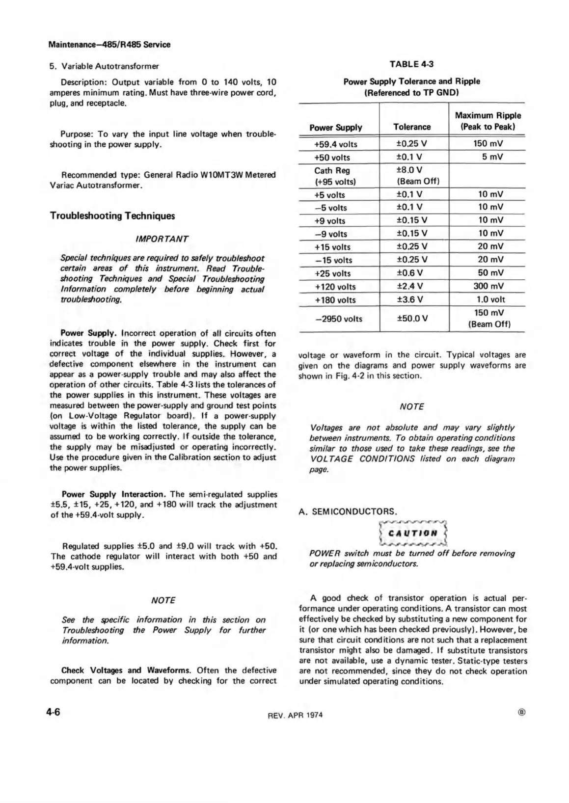
TABLE 4-3
Power Supply Tolerance and Ripple
(Referenced to TP GND)
Power Supply
Tolerance
Maximum Ripple
(Peak to Peak)
+59.4 volts
±0.25 V 150 mV
+50 volts
±0.1 V
5 mV
Cath Reg
(+95 volts)
±8.0 V
(Beam Off)
+5 volts
±0.1 V
10 mV
—5 volts
±0.1 V
10 mV
+9 volts
±0.15 V
10 mV
—9 volts
+0.15 V
10 mV
+ 15 volts
±0.25 V 20 mV
— 15 volts
±0.25 V 20 mV
+25 volts
±0.6 V 50 mV
+120 volts
±2.4 V 300 mV
+ 180 volts
±3.6 V 1.0 volt
—2950 volts
±50.0 V
150 mV
(Beam Off)
voltage or waveform in the circuit. Typical voltages are
given on the diagrams and power supply waveforms are
shown in Fig. 4-2 in this section.
NOTE
Voltages are not absolute and may vary slightly
between instruments. To obtain operating conditions
similar to those used to take these readings, see the
VOLTAGE CONDITIONS listed on each diagram
page.
A. SEMICONDUCTORS.
POWER switch must be turned o ff before removing
or replacing semiconductors.
A good check of transistor operation is actual per
formance under operating conditions. A transistor can most
effectively be checked by substituting a new component for
it (or one which has been checked previously). However, be
sure that circuit conditions are not such that a replacement
transistor might also be damaged. If substitute transistors
are not available, use a dynamic tester. Static-type testers
are not recommended, since they do not check operation
under simulated operating conditions.
4-6
REV. APR 1974

 Loading...


