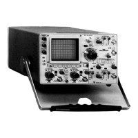
Maintenance—485/R485 Service
The reliability and accuracy of this instrument can be
maintained only if proper soldering techniques are used
when repairing or replacing parts. General soldering tech
niques which apply to maintenance of any precision
electronic equipment should be used when working on this
instrument. Use only 60/40 rosin-core, electronic-grade
solder. The choice of soldering iron is determined by the
repair to be made. When soldering on circuit boards, use a
35- to 40-watt pencil-type soldering iron with a 1/8-inch
wide, wedge-shaped tip. Keep the tip properly tinned for
best heat transfer to the solder joint. A higher wattage
soldering iron may separate the wiring from the base
material. Avoid excessive heat; apply only enough heat to
remove the component or to make a good solder joint.
Also, apply only enough solder to make a firm solder joint;
do not apply too much solder.
The Vertical Preamplifier Attenuator circuit boards
are made o f material easily damaged by excessive
heat. When soldering to these boards, do not use a
soldering iron with a rating o f more than approxi
mately 15 watts. Avoid prolonged applications o f
heat to circuit-board connections. Use only isopropyl
alcohol when cleaning this circuit board.
For metal terminals (e.g., switch terminals, potenti
ometers, etc.) a higher wattage-rating soldering iron may be
required. Match the soldering iron to the work being done.
For example, if the component is connected to the chassis
or other large heat-radiating surface, it will require a
75-watt or larger soldering iron. The pencil-type soldering
iron used on the circuit board can be used for soldering
switch terminals, potentiometers, or metal terminals
mounted in plastic holders.
Component Replacement
WARNING
Disconnect the instrument from the power source
before replacing components.
General. The exploded-view drawings associated with the
Mechanical Parts List (located at rear of manual) may be
helpful in the removal or disassembly of individual com
ponents or sub-assemblies.
WARNING
Line AC and stored DC potentials are present inside
the power unit. This instrument should be operated
with an isolation transformer whenever trouble
shooting the circuitry on that board. Follow the
recommended troubleshooting procedure given under
Special Troubleshooting Information.
Circuit Board Replacement. If a circuit board is damaged
beyond repair, the entire assembly including all soldered on
components, can be replaced. Part numbers are given in the
Parts List.
Most of the main circuit boards in this instrument plug
onto the chassis or onto other circuit boards. Use the
following procedure to remove the plug-on circuit boards
(removal instructions for the exceptions will be given later).
To remove circuit boards first remove all plug-on type
wiring and comb connectors. Plugs with more than one lead
are indexed with the arrow on the board matching the
arrow on the plug. A group of single plugs in the same area
have abbreviations of the wire color silkscreened by the pin.
a. To remove circuit boards, remove all plug-on type
wiring and comb connectors.
b. Remove all of the securing screws on the board.
c. Lift the board away from the instrument being careful
not to bend any pins protruding from the board.
d. To replace the circuit board, position it so that the
securing screws align with the mounting holes.
e. Do not tighten the securing screws until all of the
comb connectors have been inserted.
f. Uniformly tighten the securing screws. Recommended
torque is four to six inch-pounds.
TIMING BOARD REMOVAL.
a. Remove upper two rows of sweep board comb
connectors.
b. Remove Horizontal Amplifier board.
4-12
REV. APR 1974

 Loading...