Specification—485/R 485 Service
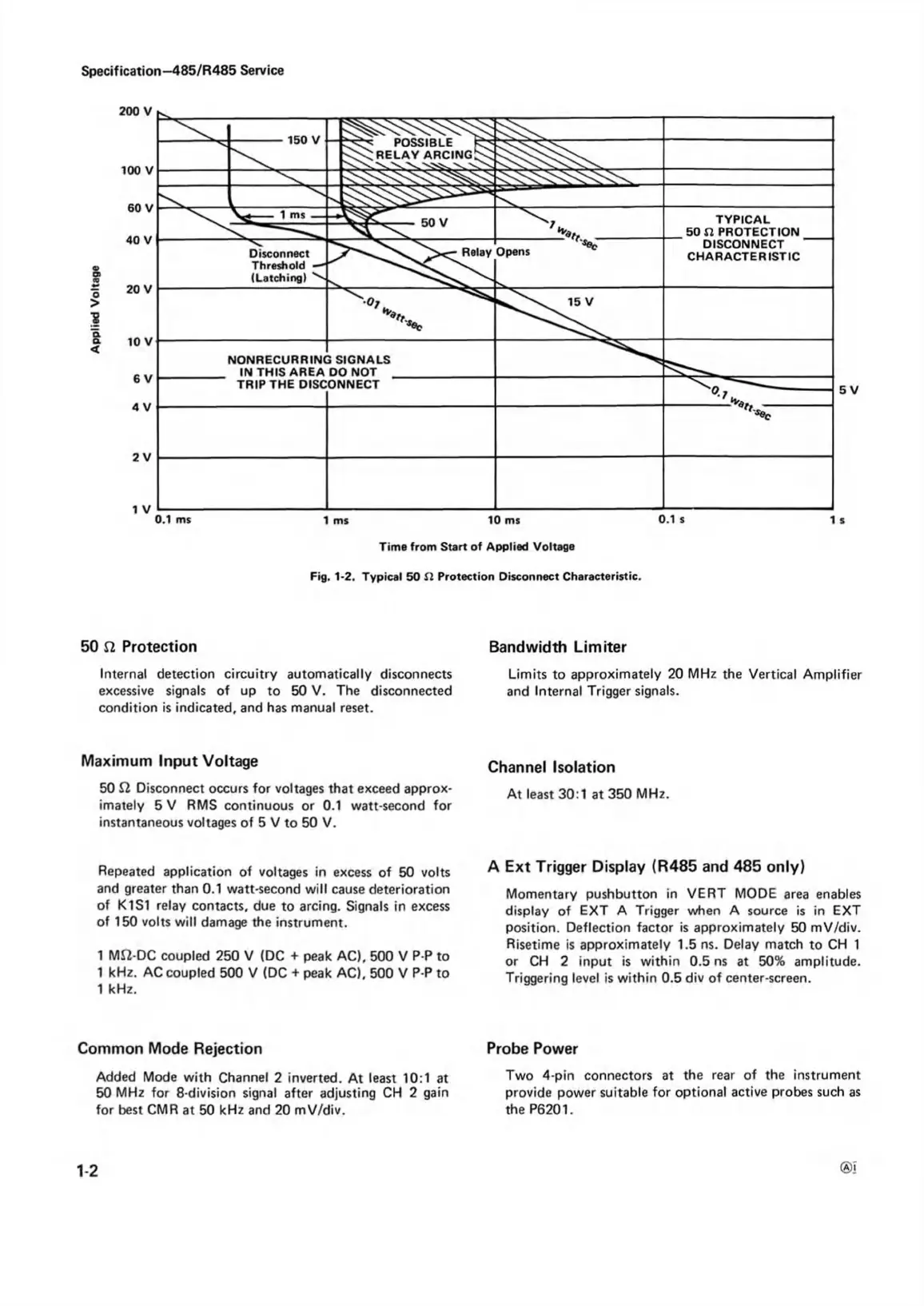
Fig. 1-2. Typical 50 S I Protection Disconnect Characteristic.
50 S2 Protection
Internal detection circuitry automatically disconnects
excessive signals of up to 50 V. The disconnected
condition is indicated, and has manual reset.
Maximum Input Voltage
50 Q. Disconnect occurs for voltages that exceed approx
imately 5 V RMS continuous or 0.1 watt-second for
instantaneous voltages of 5 V to 50 V.
Repeated application of voltages in excess of 50 volts
and greater than 0.1 watt-second will cause deterioration
of K1S1 relay contacts, due to arcing. Signals in excess
of 150 volts will damage the instrument.
1 Mft-DC coupled 250 V (DC + peak AC), 500 V P-P to
1 kHz. AC coupled 500 V (DC + peak AC), 500 V P-P to
1 kHz.
Common Mode Rejection
Added Mode with Channel 2 inverted. At least 10:1 at
50 MHz for 8-division signal after adjusting CH 2 gain
for best CMR at 50 kHz and 20 mV/div.
Bandwidth Limiter
Limits to approximately 20 MHz the Vertical Amplifier
and Internal Trigger signals.
Channel Isolation
At least 30:1 at 350 MHz.
A Ext Trigger Display (R485 and 485 only)
Momentary pushbutton in VERT MODE area enables
display of EXT A Trigger when A source is in EXT
position. Deflection factor is approximately 50 mV/div.
Risetime is approximately 1.5 ns. Delay match to CH 1
or CH 2 input is within 0.5 ns at 50% amplitude.
Triggering level is within 0.5 div of center-screen.
Probe Power
Two 4-pin connectors at the rear of the instrument
provide power suitable for optional active probes such as
the P6201.
1-2
®!

 Loading...


