Calibration— Type 503
<M)
ns>
(161
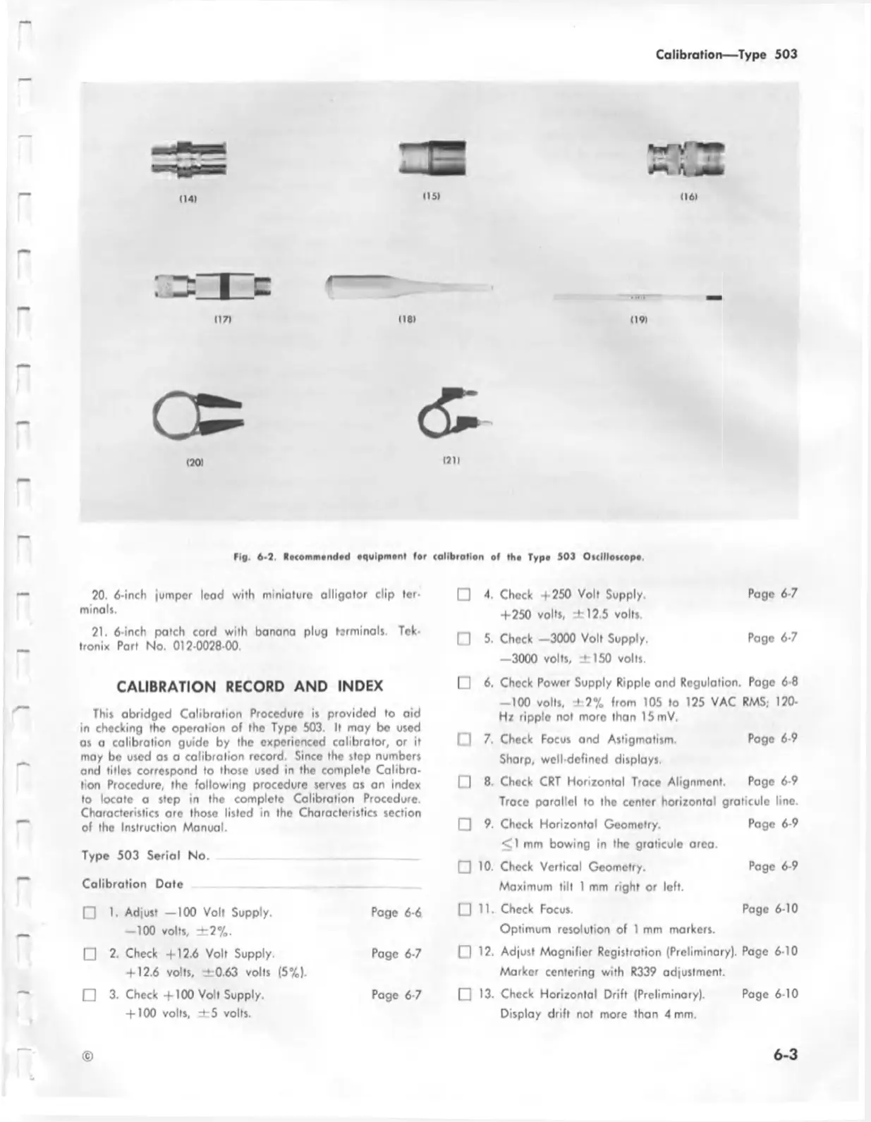
tig. 6-2. H»tomm»nd»d equipment tor calibration of tho Typo 503 Otclllotcopo
20. 6-inch jumper lead with miniature alligator clip ter
minals.
21. 6-inch patch cord with banana plug terminals. Tek
tronix Part No. 012-0028-00.
CALIBRATION RECORD AND INDEX
This abridged Calibration Procedure is provided to aid
in checking the operation of the Type 503. It may be used
as a calibration guide by the experienced calibrator, or it
may be used os a calibration record. Since the slop numbers
and titles correspond to those used in the complete Calibra
tion Procedure, the following procedure serves as an index
to locate a step in the complete Calibration Procedure.
Characteristics are those listed in the Characteristics section
of the Instruction Manual.
Type 503 Serial No.
Calibration Date
o
1. Adjust — 100 Volt Supply.
Page 6-6
—100 volts, ± 2 % .
o
2. Check +12.6 Volt Supply.
Page 6-7
+ 12.6 volts, ±0.63 volts (5%).
0
3. Check +100 Volt Supply.
Page 6-7
+ 100 volts, ± 5 volts.
□ 4. Chock +250 Volt Supply. Page 6-7
+250 vol*s, ± 1 2 5 volts.
□ 5. Chock —3000 Volt Supply. Page 6-7
—3000 volts, ± 150 volts.
□ 6. Check Power Supply Ripple and Regulation. Page 6-8
-1 0 0 volts, ± 2 % from 105 to 125 VAC RMS, 120-
Hz ripple not more than 15 mV.
0 7. Check Focus and Astigmatism. Page 6-9
Sharp, well-defined displays.
0 8. Check CRT Horizontal Trace Alignment. Page 6-9
Trace parallel to the center horizontal graticule line.
0 9. Check Horizontal Geometry. Page 6-9
<1 mm bowing in the graticule area.
0 10. Check Vertical Geometry. Page 6-9
Maximum tilt 1 mm right or left.
0 11. Check Focus. Page 6-10
Optimum resolution of 1 mm markers.
0 12. Adjust Magnifier Registration (Preliminary). Page 6-10
Marker centering with R339 adjustment.
0 13. Check Horizontal Drift (Preliminary). Page 6-10
Display drift not more than 4 mm.
©
6-3

 Loading...


