Calibration— Type 503
~ 7 ~
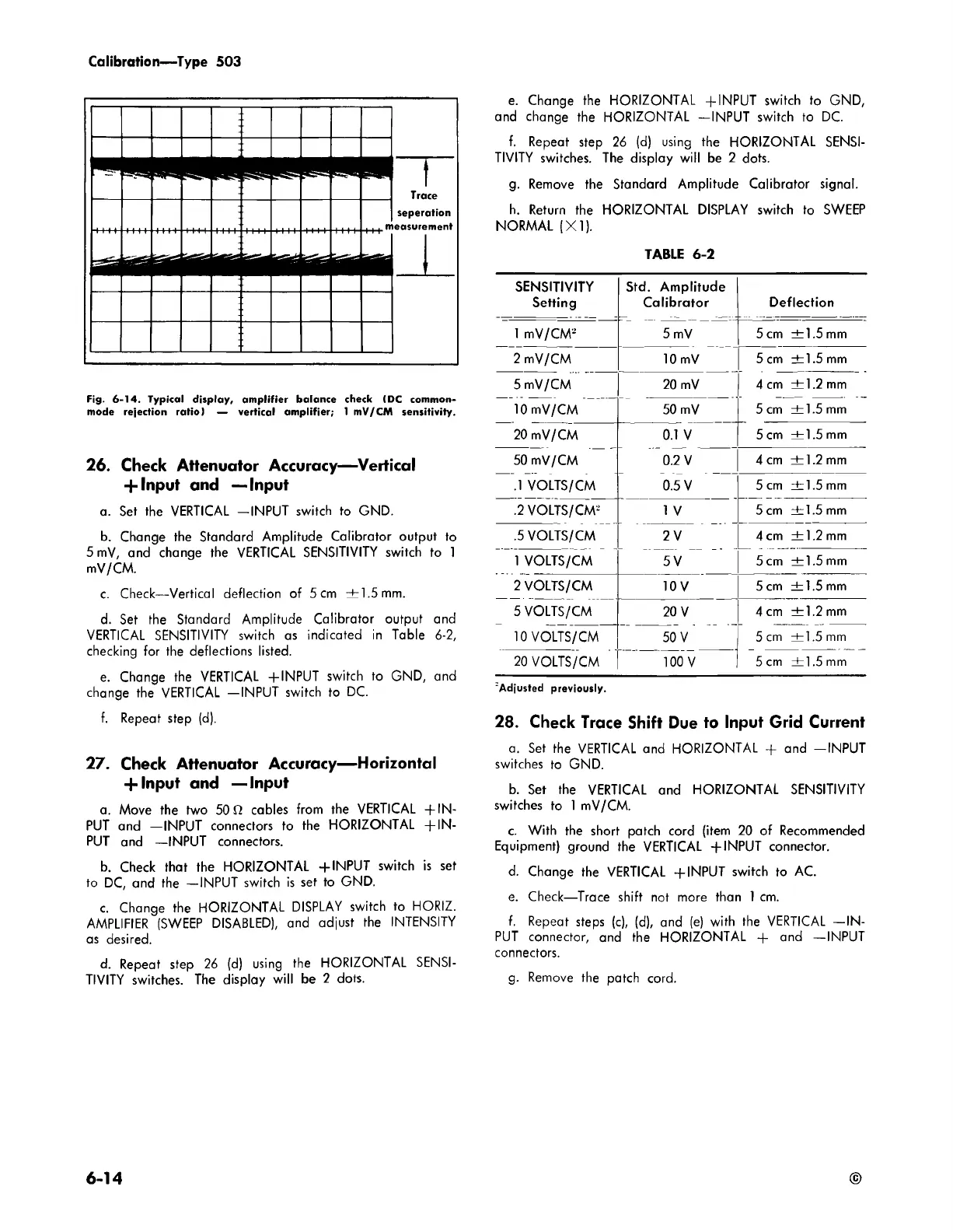
Trace
seperation
easuremenf
iM
n
Fig. 6-14. Typical display, am plifier balance check (DC common
mode rejection ratio) — vertical am plifier; 1 mV/CM sensitivity.
26. Check Attenuator Accuracy— Vertical
+ Input and — Input
a. Set the VERTICAL —INPUT switch to GND.
b. Change the Standard Amplitude Calibrator output to
5 mV, and change the VERTICAL SENSITIVITY switch to 1
mV/CM.
c. Check—Vertical deflection of 5 cm ±1 .5 mm.
d. Set the Standard Amplitude Calibrator output and
VERTICAL SENSITIVITY switch as indicated in Table 6-2,
checking for the deflections listed.
e. Change the VERTICAL +INPUT switch to GND, and
change the VERTICAL —INPUT switch to DC.
f. Repeat step (d).
27. Check Attenuator Accuracy— Horizontal
+ Input and — Input
a. Move the two 50 ft cables from the VERTICAL + IN
PUT and —INPUT connectors to the HORIZONTAL + IN
PUT and —INPUT connectors.
b. Check that the HORIZONTAL +INPUT switch is set
to DC, and the —INPUT switch is set to GND.
c. Change the HORIZONTAL DISPLAY switch to HORIZ.
AMPLIFIER (SWEEP DISABLED), and adjust the INTENSITY
as desired.
d. Repeat step 26 (d) using the HORIZONTAL SENSI
TIVITY switches. The display will be 2 dots.
e. Change the HORIZONTAL +INPUT switch to GND,
and change the HORIZONTAL —INPUT switch to DC.
f. Repeat step 26 (d) using the HORIZONTAL SENSI
TIVITY switches. The display will be 2 dots.
g. Remove the Standard Amplitude Calibrator signal.
h. Return the HORIZONTAL DISPLAY switch to SWEEP
NORMAL (X I).
TABLE 6-2
SENSITIVITY
Setting
Std. Amplitude
Calibrator
5 mV
Deflection
1 mV/CM2
5 cm ±1 .5 mm
2 mV/CM
10 mV
5 cm ± 1.5 mm
5 mV/CM 20 mV
4 cm ±1 .2 mm
10 mV/CM 50 mV
5 cm ±1.5 mm
20 mV/CM 0.1 V
5 cm ±1 .5 mm
50 mV/CM 0.2 V
4 cm ±1 .2 mm
.1 VOLTS/CM 0.5 V
5 cm ±1 .5 mm
.2 VOLTS/CM2
1 V
5 cm ± 1.5 mm
.5 VOLTS/CM
2 V
4 cm ± 1.2 mm
1 VOLTS/CM
5 V
5 cm ± 1.5 mm
2 VOLTS/CM
10 V
5 cm ±1 .5 mm
5 VOLTS/CM
20 V
4 cm ± 1.2 mm
10 VOLTS/CM
50 V
5 cm ±1.5 mm
20 VOLTS/CM
100 V
5 cm ±1 .5 mm
'Adjusted previously.
28. Check Trace Shift Due to Input Grid Current
a. Set the VERTICAL and HORIZONTAL -f and —INPUT
switches to GND.
b. Set the VERTICAL and HORIZONTAL SENSITIVITY
switches to 1 mV/CM.
c. With the short patch cord (item 20 of Recommended
Equipment) ground the VERTICAL +INPUT connector.
d. Change the VERTICAL +INPUT switch to AC.
e. Check—Trace shift not more than 1 cm.
f. Repeat steps (c), (d), and (e) with the VERTICAL —IN
PUT connector, and the HORIZONTAL -f- and —INPUT
connectors.
g. Remove the patch cord.
6 -1 4
©

 Loading...


