Calibration— Type 503
f. Check—Horizontal jitter, 2 mm or less.
g. Remove the time-mark generator signals.
51. Check Z Axis Operation
a. Change the HORIZONTAL DISPLAY switch to SWEEP
NORMAL (X I), the SWEEP TIME/CM to 1 mSEC, and the
LEVEL control clockwise to the FREE RUN position.
b. Connect a 50-ohm cable from the Standard Amplitude
Calibrator output connector to the CRT GRID binding post
of the EXTERNAL INPUT connectors (on the rear panel of
the Type 503).
c. Set the Standard Amplitude Calibrator to supply a
10-volt square wave.
d. Remove the strap connecting the CRT GRID and GND
binding posts.
e. Check—Intensity modulation of the trace should be
visible.
f. Replace the strap connecting the CRT GRID and GND
binding posts, and remove the signal from the binding post.
52 Adjust Amplitude Calibrator— 5 mV O
a. Set the VERTICAL SENSITIVITY to 1 mV/CM, and the
VERTICAL -f and —INPUT switches to DC and Trigger
control to AUTO.
b. Set the SWEEP TIME/CM to 20 ,uSEC, and the HORI
ZONTAL DISPLAY to SWEEP NORMAL (X I).
c. Set the Standard Amplitude Calibrator to supply a
5-millivolt square wave, and connect a 50-ohm cable from
the output connector to the VERTICAL + INPUT connector.
d. Connect a short patch cord from the 5 mV CAL. OUT
connector to the VERTICAL —INPUT connector.
e. Check—Trace separation at the vertical center of the
display should not exceed 1.5 mm (3%).
NOTE
See Fig. 6-32. The display amplitude in the illus
tration has been reduced with the VARIABLE con
trol to allow presentation of the display within
the graticule area; the actual display with the
control settings outlined in steps (a) through
(d) should have an amplitude of 10cm, with the
center trace either a single line, or separated by
the amount of difference between the Standard
Amplitude Calibrator voltage and the Type 503
CAL. OUT voltage.
f. Adjust CAL. ADJ. R880 for no trace separation at the
center of the display.
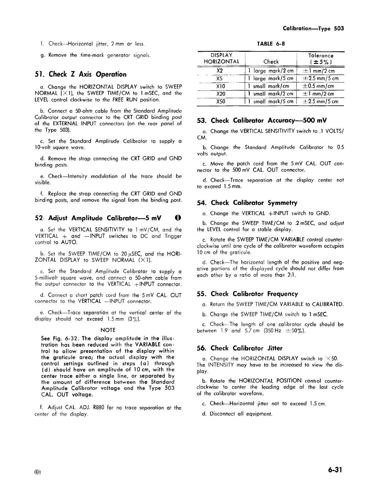
TABLE 6-8
DISPLAY
HORIZONTAL
Check
Tolerance
(±5%)
X2
1 large mark/2 cm
± 1 mm/2 cm
X5
1 large mark/5 cm ± 2.5 mm/5 cm
X10
1 small mark/cm +0 .5 mm/cm
X20
1 small mark/2 cm
± 1 mm/2 cm
X50 1 small mark/5 cm ±2 .5 mm/5 cm
53. Check Calibrator Accuracy— 500 mV
a. Change the VERTICAL SENSITIVITY switch to .1 VOLTS/
CM.
b. Change the Standard Amplitude Calibrator to 0.5
volts output.
c. Move the patch cord from the 5 mV CAL. OUT con
nector to the 500 mV CAL. OUT connector.
d. Check—Trace separation at the display center not
to exceed 1.5 mm.
54. Check Calibrator Symmetry
a. Change the VERTICAL + INPUT switch to GND.
b. Change the SWEEP TIME/CM to .2 mSEC, and adjust
the LEVEL control for a stable display.
c. Rotate the SWEEP TIME/CM VARIABLE control counter
clockwise until one cycle of the calibrator waveform occupies
10 cm of the graticule.
d. Check—The horizontal length of the positive and neg
ative portions of the displayed cycle should not differ from
each other by a ratio of more than 2:1.
55. Check Calibrator Frequency
a. Return the SWEEP TIME/CM VARIABLE to CALIBRATED.
b. Change the SWEEP TIME/CM switch to 1 mSEC.
c. Check—The length of one calibrator cycle should be
between 1.9 and 5.7 cm (350 Hz ±50% ).
56. Check Calibrator Jitter
a. Change the HORIZONTAL DISPLAY switch to X50.
The INTENSITY may have to be increased to view the dis
play.
b. Rotate the HORIZONTAL POSITION control counter
clockwise to center the leading edge of the last cycle
of the calibrator waveform.
c. Check— Horizontal jitter not to exceed 1.5 cm.
d. Disconnect all equipment.
©1
6-31

 Loading...


