Calibration— Type 503
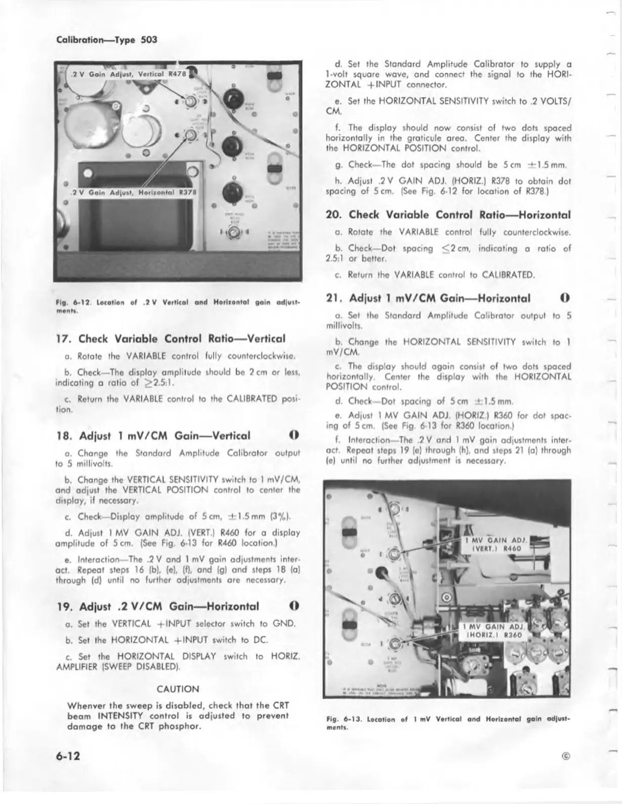
Fig. 6-12. location of ,2 V Vottical and H otltonlal gain ad|u tl-
monlt.
17. Check Variable Control Ratio— Vertical
a. Rotate the VARIABLE control fully counterclockwise.
b. Check—The display amplitude should be 2 cm or less,
indicating a ratio of ^2.5:1.
c. Return tho VARIABLE control to the CALIBRATED posi
tion.
18. Adjust 1 mV/CM Gain— Vertical O
a. Change the Standard Amplitude Calibrator output
to 5 millivolts.
b. Change the VERTICAL SENSITIVITY switch to I mV/CM,
and adjust the VERTICAL POSITION control to center tho
display, if necessary.
c. Check—Disploy amplitude of 5 cm, ± 1 .5 mm (3%).
d. Adjust 1 MV GAIN ADJ. (VERT.) R460 for a display
amplitude of 5 cm. (See Fig. 6-13 for R460 location.)
e. Interaction—The .2 V and 1 mV gain adjustments inter
act. Repeat steps 16 |b), (e), (f), and (g) and steps 18 (a)
through (d) until no further adjustments are necessary.
19. Adjust .2 V/CM Gain— Horizontal O
a. Set the VERTICAL ± INPUT selector switch to GND.
b. Set the HORIZONTAL + INPUT switch to DC.
c. Set the HORIZONTAL DISPLAY switch to HORIZ.
AMPLIFIER (SWEEP DISABLED)
CAUTION
Whenver the sweep is disabled, check that the CRT
beam INTENSITY control is adjusted to prevent
damage to the CRT phosphor.
d. Set the Standard Amplitude Calibrator to supply a
1-volt square wave, and connect the signal to the HORI
ZONTAL -f INPUT connector.
e. Set the HORIZONTAL SENSITIVITY switch to .2 VOLTS/
CM.
f. The display should now consist of two dots spaced
horizontally in the graticule area. Center the display with
the HORIZONTAL POSITION control.
g. Check—The dot spacing should be 5 cm ± 1.5 mm.
h. Adjust .2 V GAIN ADJ. (HORIZ.) R378 to obtain dot
spacing of 5 cm. (See Fig. 6-12 for location of R378.)
20. Check Variable Control Ratio— Horizontal
a. Rotato the VARIABLE control fully counterclockwise.
b. Check— Dot spacing < 2 cm, indicating a ratio of
2.5:1 or better.
c. Return the VARIABLE control to CALIBRATED,
21. Adjust 1 mV/CM Gain— Horizontal O
a. Set the Standard Amplitude Calibrator output to 5
millivolts.
b. Change the HORIZONTAL SENSITIVITY switch to 1
mV/CM.
c. The display should again consist of two dots spaced
horizontally. Center the display with the HORIZONTAL
POSITION control.
d. Check—Dot spacing of 5 cm ± 1.5 mm.
o. Adjust 1 MV GAIN ADJ. (HORIZ.) R360 for dot spac
ing of 5 cm. (Soe Fig 6-13 for R360 location.)
f. Interaction—The 2 V and 1 mV gain adjustments inter
act. Repeot steps 19 (o) through (h), and steps 21 (a) through
(e) until no further adjustment is necessary.
Fig. 6-13. Location of 1 mV Vortical and Horizontal gain odjust
monts.
6-12 ©

 Loading...


