C alibration— Type 503
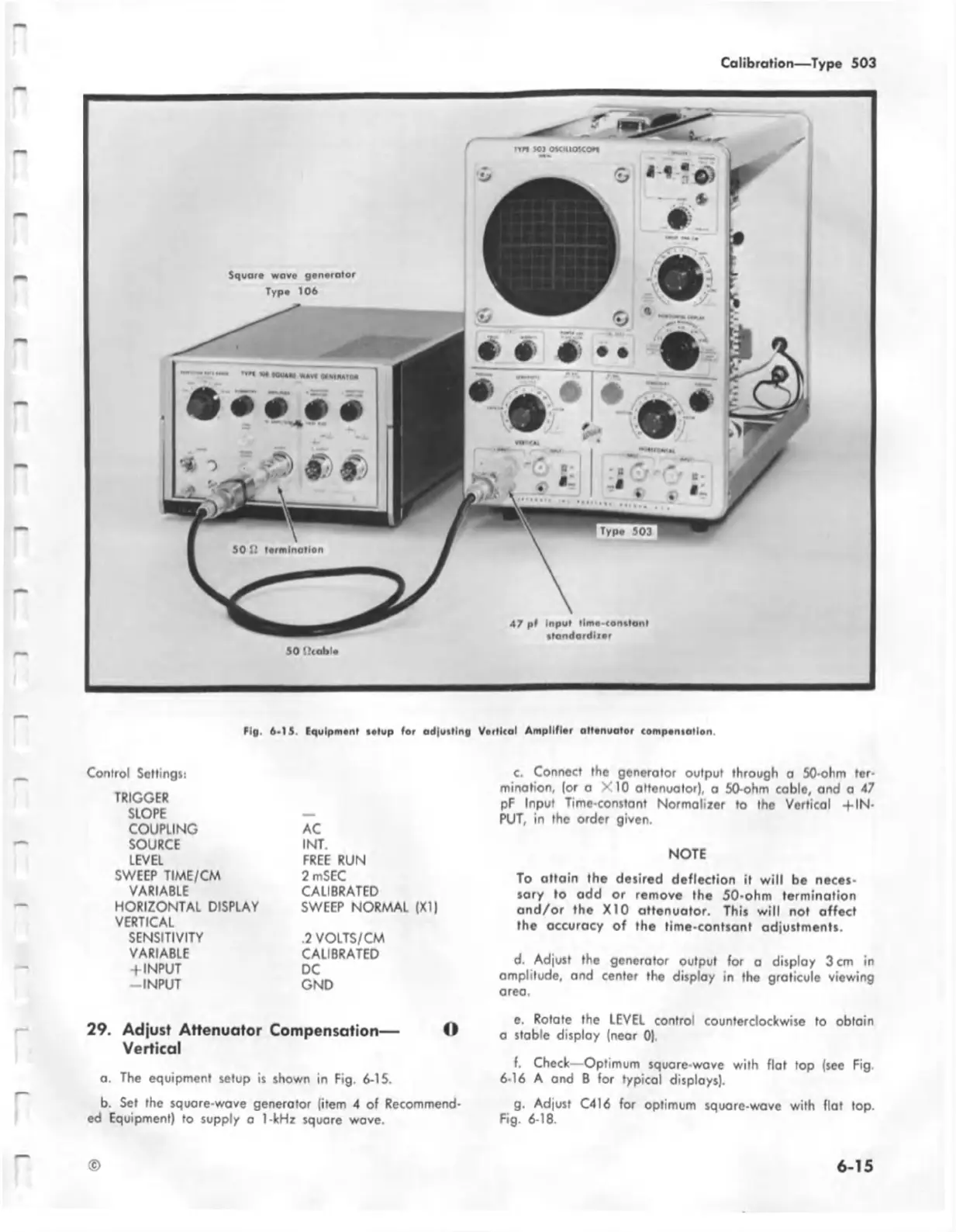
tig . 6 -1S. Equipment i*tu p (or ad|u itlng Vortical A m pllflor alU nuator com poniatlon.
Control Settings:
TRIGGER
SLOPE
COUPLING
SOURCE
LEVEL
SWEEP TIME/CM
VARIABLE
HORIZONTAL DISPLAY
VERTICAL
SENSITIVITY
VARIABLE
+ INPUT
-IN PU T
AC
INT.
FREE RUN
2 mSEC
CALIBRATED
SWEEP NORMAL (XI)
.2 VOLTS/CM
CALIBRATED
DC
GND
c. Connect the generator output through a 50-ohm ter
mination, (or a X 10 attenuator), o 50-ohm cable, and a 47
pF Input Time-constant Normalizer to the Vertical + IN
PUT, in the order given.
NOTE
To attain the desired deflection it w ill be neces
sary to add or remove the 50-ohm termination
a nd /o r the X I0 attenuator. This w ill not affect
the accuracy of the time-contsant adjustments.
d. Adjust the generator output for a display 3 cm in
amplitude, and center the display in the graticule viewing
area.
29. Adjust Attenuator Compensation— O
Vertical
a. The equipment setup is shown in Fig. 6-15.
e. Rotate the LEVEL control counterclockwise to obtain
a stable display (near 0).
f. Check—Optimum square-wave with flat top (see Fig.
6-16 A and B for typical displays).
b. Set the square-wave generator (item 4 of Recommend
ed Equipment) to supply a 1-kHz square wave.
g. Adjust C416 for optimum square-wave with flat top.
Fig. 6-18.
©
6-15

 Loading...


