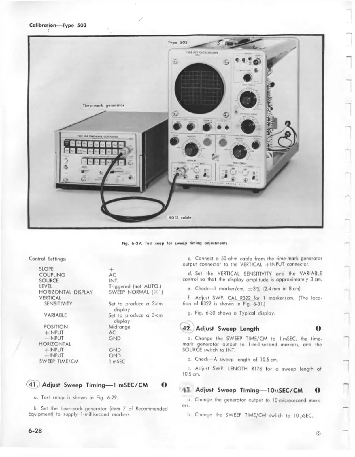
Mg. 6 -7 9 . Ten ic u p lo r iw ee p lim in g a d|u tlm e n lt,
Control Settings:
SLOPE
COUPLING
SOURCE
LEVEL
HORIZONTAL DISPLAY
VERTICAL
SENSITIVITY
VARIABLE
POSITION
+ INPUT
-IN PU T
HORIZONTAL
+ INPUT
-IN PUT
SWEEP TIME/CM
+
AC
I NT.
Triggered (not AUTO.)
SWEEP NORMAL (X 1)
Set to produce o 3 cm
display
Set to produce o 3-cm
display
Midrange
AC
GND
GND
GND
1 mSEC
41. Adjust Sweep Timing— 1 mSEC/CM O
a. Test setup is shown in Fig. 6-29.
b. Set the time-mark generator (item 7 of Recommended
Equipment) to supply 1-millisecond markers.
c. Connect a 50-ohm cable from the lime-mark generator
output connector to the VERTICAL + INPUT connector.
d. Set the VERTICAL SENSITIVITY and the VARIABLE
control so that the display amplitude is approximately 3 cm.
e. Chock— 1 marker/cm, ± 3 % (2.4 mm in 8 cm).
f. Adjust SWP. CAL R322 for I marker/cm. (The loca
tion of R322 is shown in Fig. 6-31.)
g. Fig. 6-30 shows a Typical display.
42 J Adjust Sweep Length ©
o. Change the SWEEP TIME/CM to I mSEC, the lime-
mark generator output to I-millisecond markers, and the
SOURCE switch to INT.
b. Check—A sweep length of 10.5 cm.
c. Adjust SWP. LENGTH R176 for a sweep length of
10.5 cm.
Adjust Sweep Timing— 10/t.SEC/CM ©
o. Change the generator output to 10-microsecond mark
ers.
b. Change the SWEEP TIME/CM switch to 10/iSEC.
©
6 -2 8

 Loading...


