Calibration— Type 503
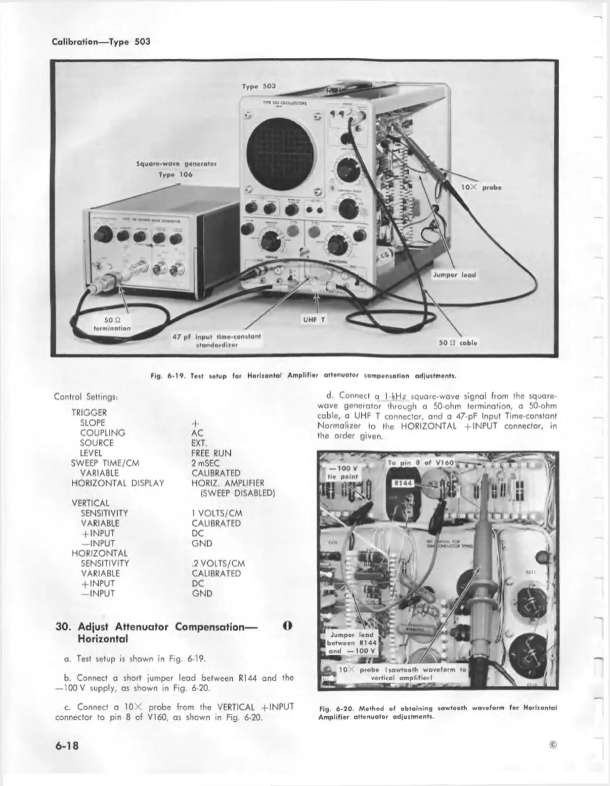
Fig. 6-19. Tail sotup for H o rlio nlal A m plifier attenuator compensation adjustments.
Control Setting*:
TRIGGER
SLOPE
COUPLING
SOURCE
LEVEL
SWEEP TIME/CM
VARIABLE
HORIZONTAL DISPLAY
VERTICAL
SENSITIVITY
VARIABLE
+ INPUT
-INPU T
HORIZONTAL
SENSITIVITY
VARIABLE
-f INPUT
-INPU T
+
AC
EXT.
FREE RUN
2 mSEC
CALIBRATED
HORIZ. AMPLIFIER
(SWEEP DISABLED)
1 VOLTS/CM
CALIBRATED
DC
GND
.2 VOLTS/CM
CALIBRATED
DC
GND
30. Adjust Attenuator Compensation— O
Horizontal
a. Test setup is shown in Fig. 6-19.
b. Connect a short jumper lead between R144 and the
— 100 V supply, as shown in Fig. 6-20.
d. Conned a I-kHz square-wave signal from the square-
wave generator through a 50-ohm termination, a 50-ohm
cablo, a UHF T connector, and a 47-pF Input Time-constant
Normalizer to tho HORIZONTAL -f INPUT connector, in
the order given.
c. Connect a 10X probe from the VERTICAL + INPUT
connector to pin 8 of V I60, as shown in Fig. 6-20.
Fig. 6-20. Method of obtaining sawtooth waveform for Horiiontal
Am plifier attenuator adjustments.
6 -1 8
©

 Loading...


