Calibration— Type 503
50 it cablet
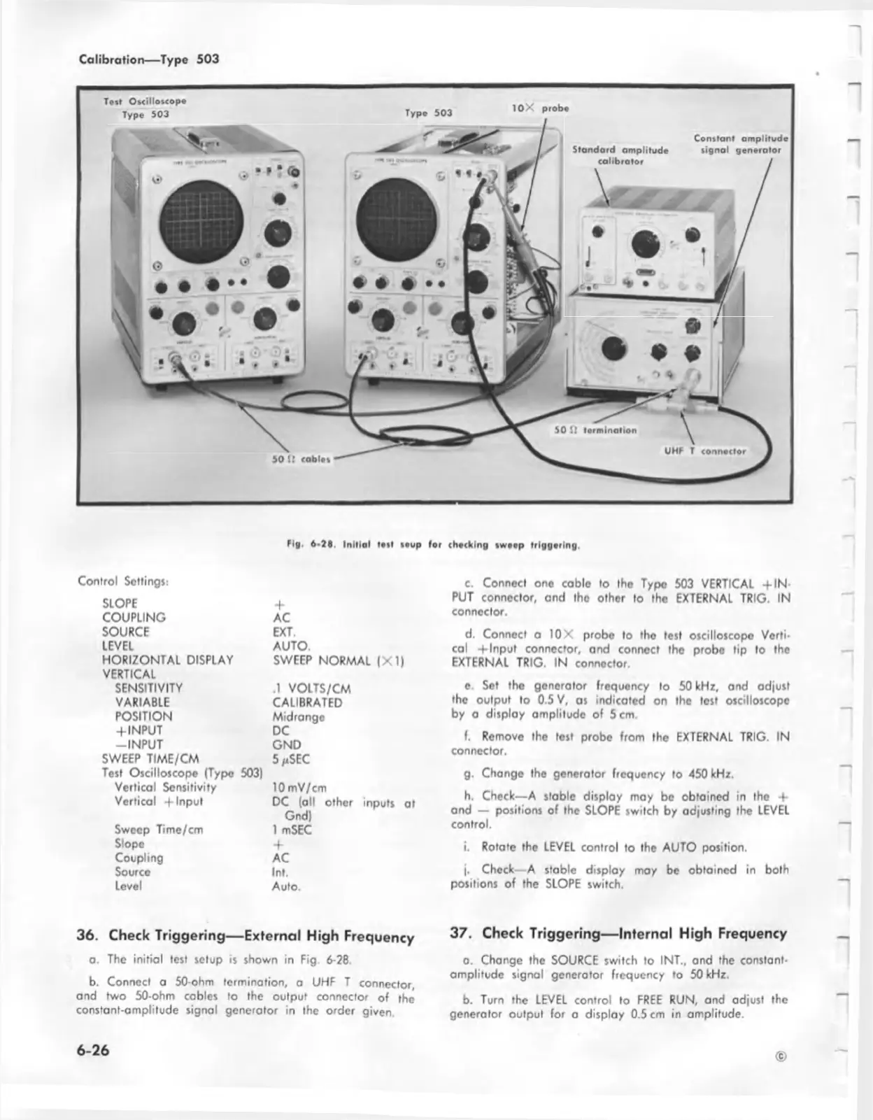
Tost O»<illo*<op«
Type 503
Type 503
1 0 X probe
Standard amplitude
calibrator
Constant amplitude
signal generator
tig . 6-38. Initial le t! teup for checking tweep triggering.
Control Sottingj:
SLOPE
COUPLING
SOURCE
LEVEL
HORIZONTAL DISPLAY
VERTICAL
SENSITIVITY
VARIABLE
POSITION
+ INPUT
-IN P U T
SWEEP TIME/CM
Test Oscilloscope (Type
Vertical Sensitivity
Vertical -f Input
Sweep Time/cm
Slope
Coupling
Source
Level
+
AC
EXT.
AUTO.
SWEEP NORMAL |X 1)
.1 VOLTS/CM
CALIBRATED
Midrange
DC
GND
5/cSEC
10 mV/cm
DC (all other inputs at
Gnd)
1 mSEC
+
AC
Ini.
Auto.
c. Connect one coble to the Type 503 VERTICAL -flN
PUT connector, and the other to the EXTERNAL TRIG. IN
connector.
d. Connect a 10 X probe to the test oscilloscopo Verti
cal -f Input connector, and connect the probe tip to the
EXTERNAL TRIG. IN connector.
e. Set the generator frequency to 50 kHz, and adjust
the output to 0.5 V, as indicated on the test oscilloscope
by a display amplitude of 5 cm.
f. Remove the test probe from the EXTERNAL TRIG. IN
connector.
g. Change the generator frequency to 450 kHz.
h. Check— A stable display may be obtained in the +
and — positions of the SLOPE switch by adjusting the LEVEL
control.
i. Rotate the LEVEL control to the AUTO position.
j. Check—A stable display may be obtained in both
positions of the SLOPE switch.
36. Check Triggering— External High Frequency
a. The initial test setup is shown in Fig 6-28.
b. Connect a 50-ohm termination, a UHF T connector,
and two 50-ohm cables to the output connector of the
constant-amplitude signal generator in the order given.
37. Check Triggering— Internal High Frequency
o. Change the SOURCE switch to INT., and the constant-
amplitude signal generator frequency to 50 kHz.
b. Turn the LEVEL control to FREE RUN, and adjust the
generator output for a display 0.5 cm in amplitude.
6 -2 6

 Loading...


