Calibration— Type 503
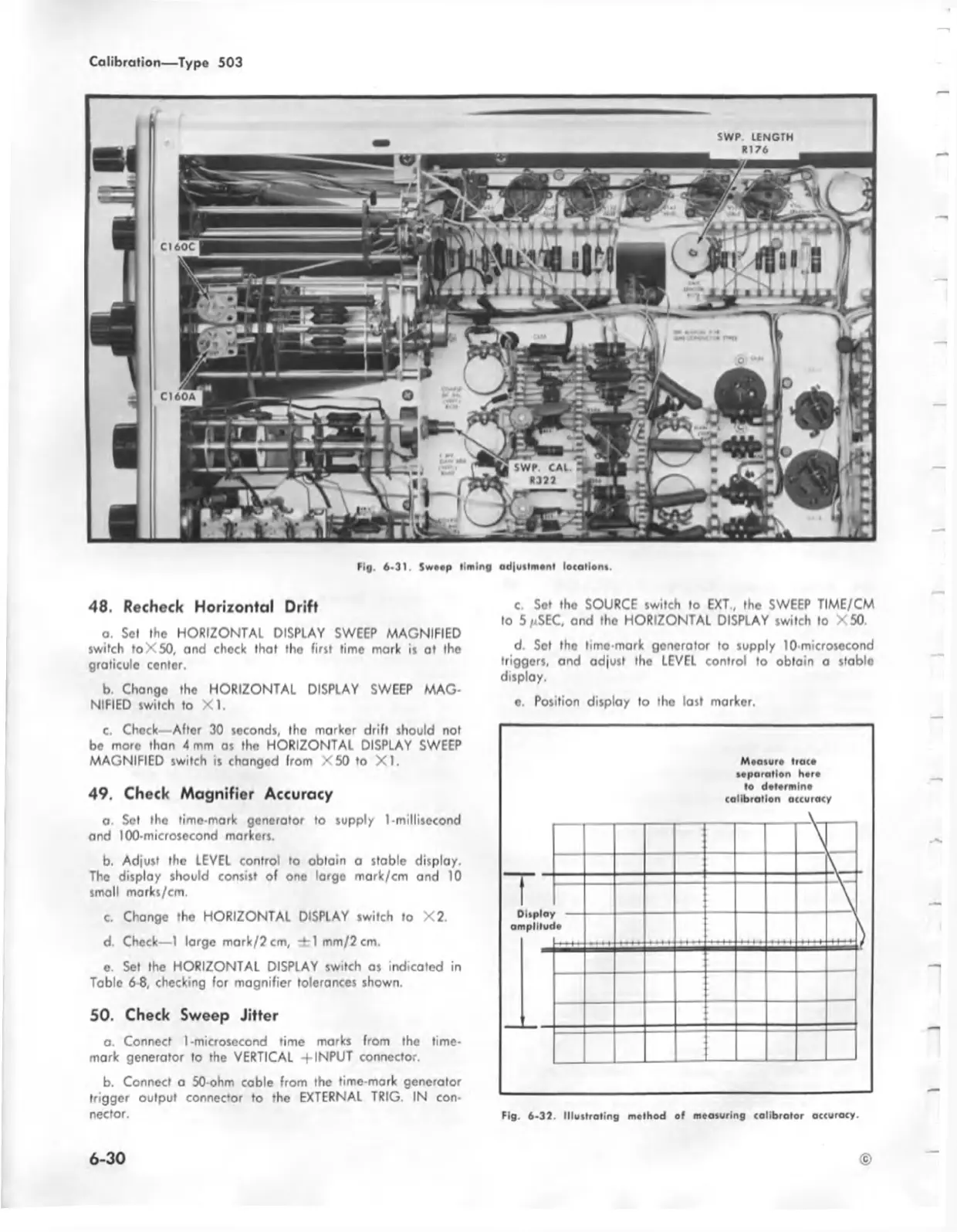
Fig. 6 -3 1. Swo.p lim ing odjutlrntn l location*.
48. Recheck Horizontal Drift
a. Set the HORIZONTAL DISPLAY SWEEP MAGNIFIED
switch foX50, and check that iho first time mark is at the
graticule center.
b. Change the HORIZONTAL DISPLAY SWEEP MAG
NIFIED switch to X I.
c. Chock—After 30 seconds, the marker drift should not
be more than 4 mm as the HORIZONTAL DISPLAY SWEEP
MAGNIFIED switch is changed from X 50 to X I.
49. Check Magnifier Accuracy
a. Set the time-mark generator to supply I-millisecond
and 100-microsecond markers.
b. Adjust the LEVEL control to obtain a stable display.
The display should consist of one largo mark/cm and 10
small marks/cm.
c. Change the HORIZONTAL DISPLAY switch to X2.
d. Check— 1 large mark/2cm, -irl mm/2cm.
c. Set the HORIZONTAL DISPLAY switch os indicated in
Table 6-8, checking for magnifier tolerances shown.
50. Check Sweep Jitter
o. Connect 1-microsecond time marks from the time-
mark generator to the VERTICAL + INPUT connector.
b. Connect a 50-ohm cable from the time-mark generator
trigger output connector to the EXTERNAL TRIG. IN con
nector.
c. Sot tho SOURCE switch to EXT , the SWEEP TIME/CM
to 5 /.SEC, and the HORIZONTAL DISPLAY switch to X50.
d. Set the lime-mark generator to supply 10-microsecond
triggers, and adjust tho LEVEL control to obtain a stablo
display.
e. Position display to tho last marker.
Measure trace
separation here
to determine
calibration accuracy
— ;
--------
\
£
T 1
Display
amplitud
\
)
•
Fig. 6-32. Illustrating method of measuring calibrator accuracy.
6-30
©

 Loading...


