C alibration— Type 503
s. Check—Square front corner on waveform, with over
shoot or rounding not exceeding 2% of display amplitude.
t. Adjust C414C for optimum front corner of waveform.
u. Check the square wave response in all remaining
VERTICAL SENSITIVITY switch positions, alternately switch
ing between the 2 mSEC and .1 mSEC positions of the
SWEEP TIME/CM switch.
NOTE
All attenuator compensation adjustments or checks
are made with a display am plitude of 3 cm. Insert
or remove attenuation a n d /o r adjust the signal
generator output to maintain this display am pli
tude.
v. Change the SWEEP TIME/CM switch to 2 mSEC.
w. Change the VERTICAL -f INPUT switch to GND, the
VERTICAL —INPUT switch to DC, and move the generator
signol from the VERTICAL —INPUT connector to tho VER
TICAL —INPUT connector.
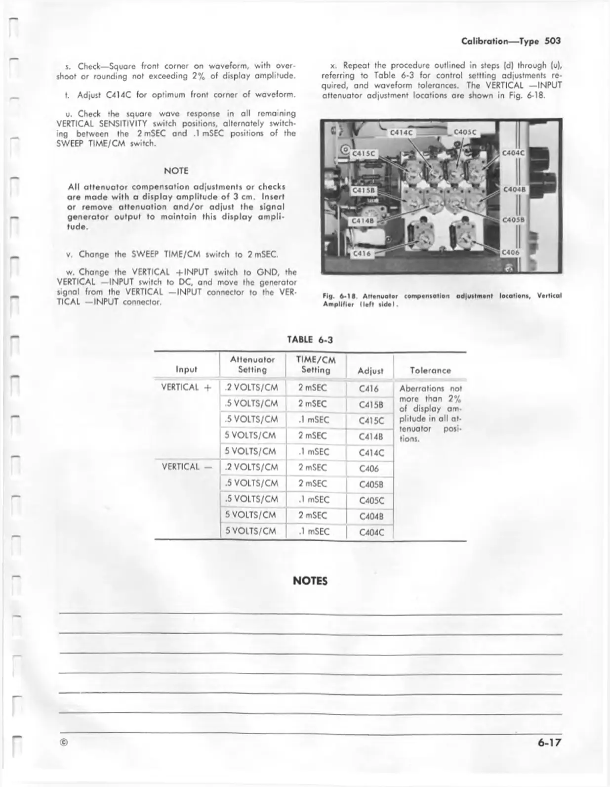
x. Repeat the procedure outlined in steps (d) through (u),
referring to Table 6-3 for control settling adjustments re
quired, and waveform tolerances. The VERTICAL —INPUT
attenuator adjustment locations are shown in Fig. 6-18.
Fig. 6-1 1 . Atte nu ator com pensation adjustm e nt locations, Vortical
A m p lifie r H e ft side I.
TABLE 6-3
Input
Attenuator
Setting
TIME/CM
Setting
Adjust
Tolerance
VERTICAL + .2 VOLTS/CM
2 mSEC
C416
Aberrations not
more than 2%
of display am-
pliludo in all at-
tenuator posi-
tions.
.5 VOLTS/CM
2 mSEC
C415B
.5 VOLTS/CM
.1 mSEC
C415C
5 VOLTS/CM
2 mSEC
C414B
5 VOLTS/CM
.1 mSEC
C414C
VERTICAL -
.2 VOLTS/CM
2 mSEC
C406
.5 VOLTS/CM
2 mSEC
C405B
.5 VOLTS/CM
.1 mSEC
C405C
5 VOLTS/CM
2 mSEC
C404B
5 VOLTS/CM
.1 mSEC
C404C
NOTES

 Loading...


