Specifications
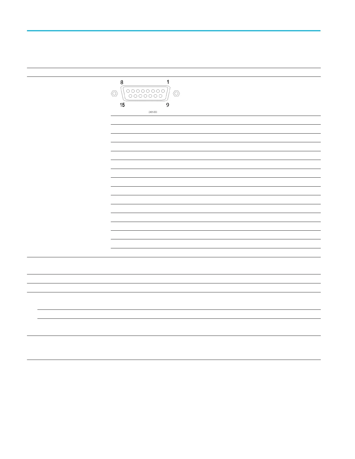
Table 29: Patte
rn Jump In connector
Characteristics Description
Connector type 15-pin D-sub female connector on rear panel.
Pin assignm
ents
1
GND
2 Data bit 0, input
3 Data bit 1, input
4Databit2
, i nput
5
Data bit 3, input
6
GND
7
Strobe, input
8
GND
9
GND
10 Data bit 4, input
11 Data b
it 5, input
12 Data bit 6, input
13 Data bit 7, input
14
GND
Input signal
pin assignment
15
GND
In
put lev els
3.3 V LVCMOS.
5 V TTL compliant.
Input impedance
1kΩ resistor pull down to GND.
Number of jump destinations
256
Strobe
Polarity Data is clocked in on negative edge.
Minimum pulse width 64 ns
Setup and hold Setup: 5 ns.
Hold: 5 ns.
Holdoff time
>18 μs
Strobe hold off is the amount of delay required at the end of a waveform before another strobe
pulse c an be processed.
20 AWG5200 Series Technical Reference

 Loading...


