Performance tests
20. Repeat ste
ps 9 through 17 for the CH1 (–) connector.
21. Repeat steps 3 through 20 until all channels are checked, modifying the
instruct
ions for the channel under test.
22. Press the AWG front panel All Outputs Off button (or click All Outputs Off
on the Ho
me screen) to disable the outputs (front panel light on).
23. Disconnect the test setup.
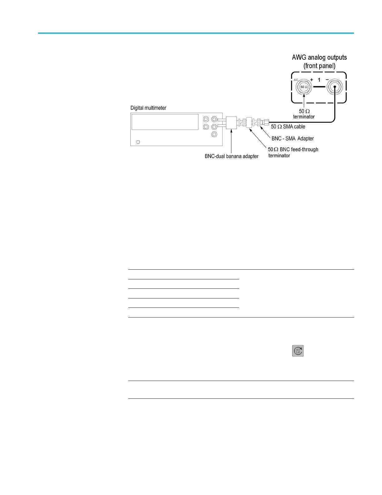
Analog offset accuracy (DC output paths)
Requi
red equipment
Prere
quisites
Digital multimeter
BNC-dual banana adapter
50 Ω BNC feed-through terminator
SMA female-BNC male adapter
50 Ω SMA terminator
AWG pr
eparation and load test
waveforms(See page 42, Prerequisites.)
Termination resistance measurement
proc
edure
Before starting this procedure, ensure you have the “Term R” value used in the
ca
lculations. (See page 44, Termination resistance measurement.)
1. Click the Reset to Default Setup button in the toolbar
.
2. Load the test waveform PV_DC_Zero.wfmx into the Waveform List.
NOTE. Test waveforms are located at
C:\Program Files\Tektronix\AWG5200\Samples\PV.
3. From the Waveform List window, assign the waveform PV_DC_Zero.wfmx
to Channel 1.
AWG5200 Series Technical Reference 51

 Loading...


