Removal and Installation Procedures
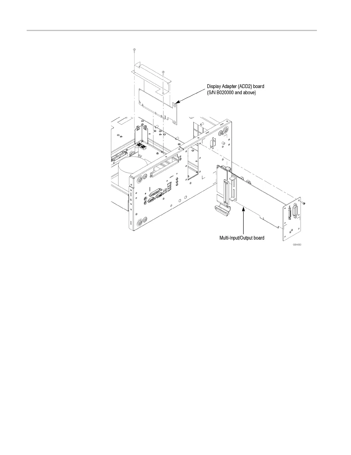
Figure 4-15: Multi-Input/Output and Display Adapter board removal (AWG7000B
Serie
s)
Multi-Input/Output Board
(Seri
al Numbers B020000
and Higher)
You need a screwdriver with a T-15 Torx tip (items 1 and 2).
Removal. To remove the Multi-Input/Output board, follow these steps: (See
Figure 4-15.)
1. Remove the handle unit, snaps, cosmetic covers, front-trim unit, EMI covers,
MIO board enforcement bracket, h ard disk assembly, and drive-bay module.
2. Orient the instrument so that the bottom is on the work surface and the rear is
facing you.
3. Disconnect the cables from J360, J600, J610, and J680 on the
Multi-Input/Output board.
4. Remove the screws securing the Multi-Input/Output board to the chassis.
5. Carefully pull up on the board to loosen it from the Processor board.
4–32 AWG7000B and AWG7000C Series Service Manual

 Loading...


