Adjustment Procedures
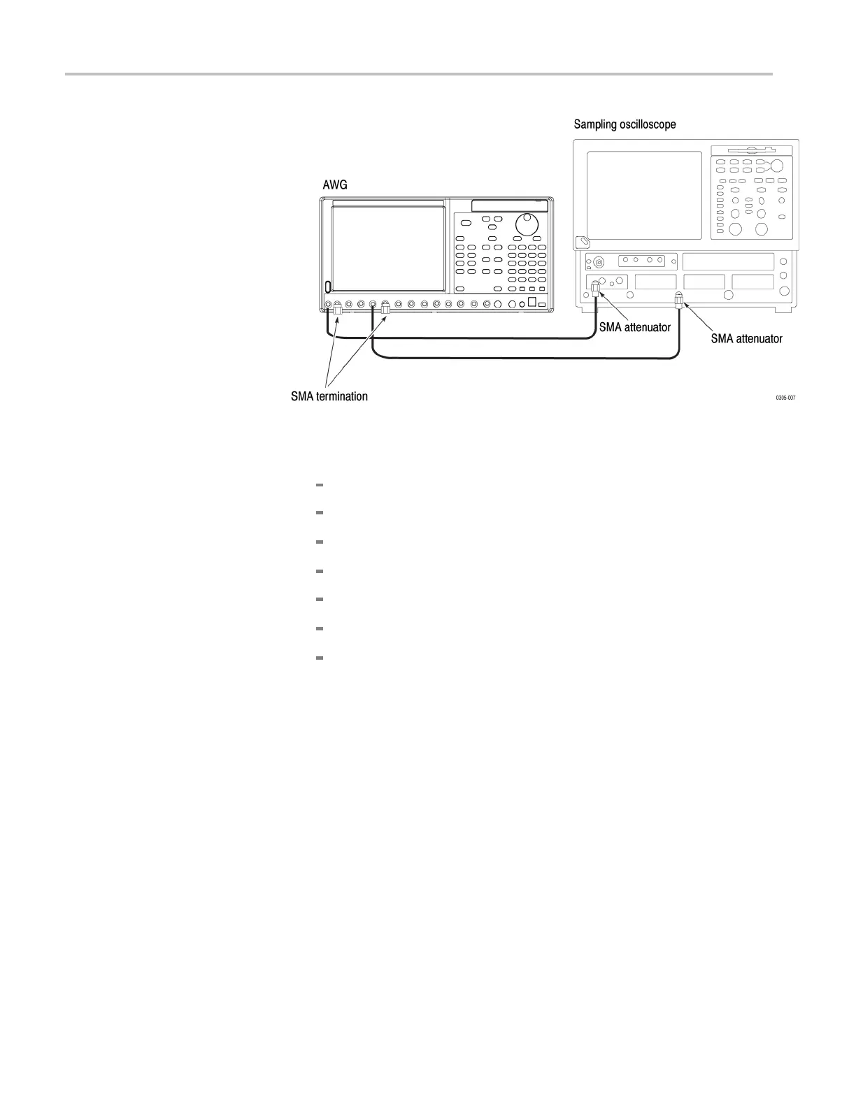
Figure 3-6: Interleave calibration initial hookup
b. Set the sampling oscilloscope as follows:
Vertical External Attenuation: 12 dB
Vertical Scale: 100 mV/div
Horizontal Scale: 1 ns/div
Horizontal Timebase Mode: Lock to INT. 10 MHz
Trigg
er: External Direct Input, Level 50%
Acquisition: Average 64
Measurement: C1 High Level, C1 Low Level, R1-Rise to C1-Rise
Delay
2. Click the Interleave... button in the AwgService UI window to display the
Interleave Calibration window. (See Figure 3-7.)
3–12 AWG7000B and AWG7000C Series Service Manual

 Loading...


