Specifications
Display Specifications
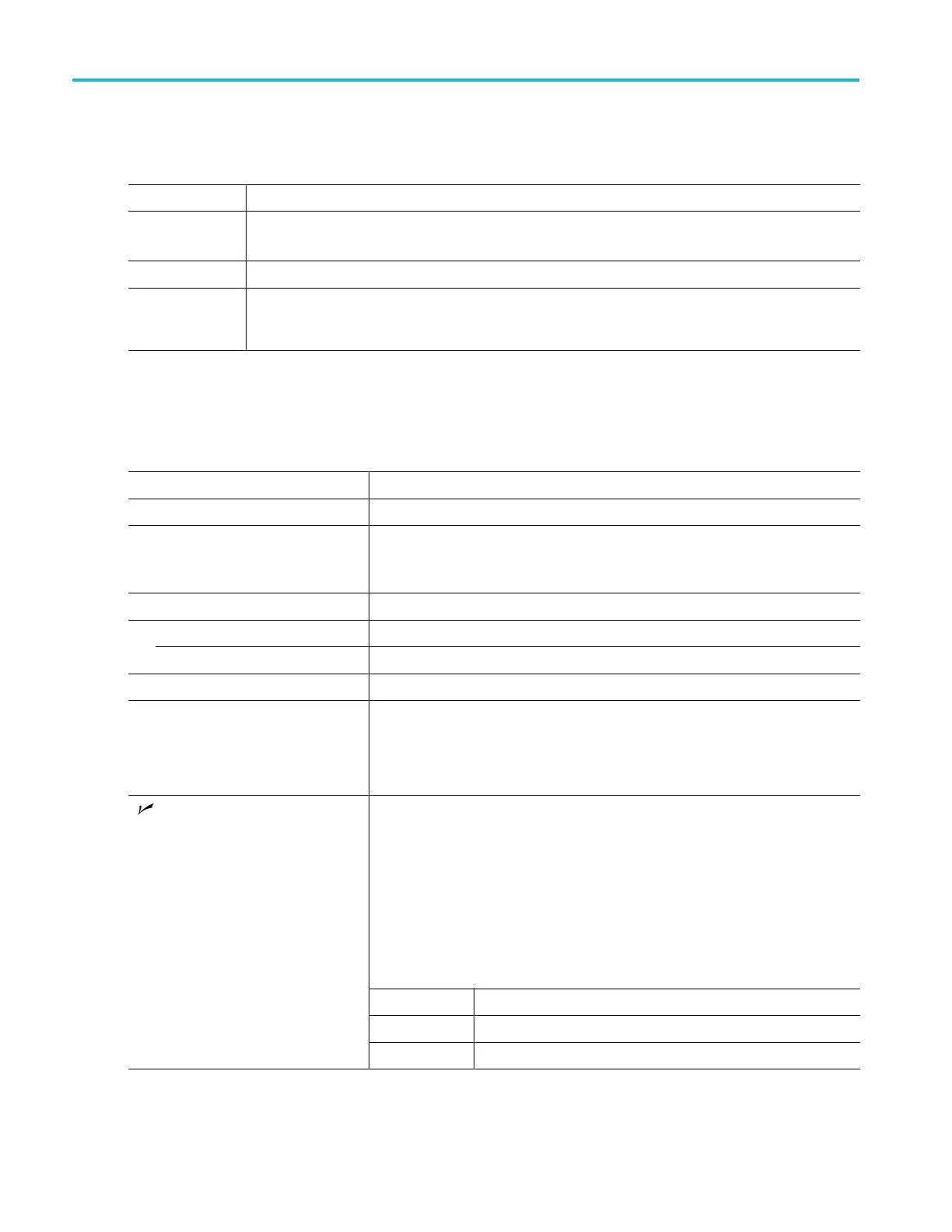
Table 7: Display specifications
Characteristic Description
Display type
9” WVGA LCD display
Display Area: 198 mm (H) X 111.696 mm (V).
Display resolution
800 X 480 pixels, each m ade up of 3 vertical stripe sub-pixels colored red, green, and blue
Minimum
Luminance,
typical
300 cd/m
2
at IBL = 5.0 m A
rms
/lamp
Input/Output Port Specifications
Table 8: Input/Output port specifications
Characteristic Description
Ethernet interface Standard on all models: 10/100 Mb/s
GPIB interface Available as an optional accessory that connects to USB Device and USB Host port,
with the TEK-USB-488 GPIB to USB Adapter
Control interface is incorporated in the instrument user interface
USB interface 1 Device and 2 Host connectors (all models)
Device port
One USB 2.0 High Speed port. Also supports Full Speed and Slow Speed Modes
Host ports
Two USB 2.0 High Speed ports. One on front, one on rear
Video signal output
A 15 pin, VGA RGB-type connector
Probe compensator output voltage and
frequency, typical
Output voltage:
Default Mode: 0 to 2.5 V amplitude, ±2% (Source Impedance of 1 K)
TPPXXXX Cal Mode: 0 to 2.5 V amplitude, ±5% (Source Impedance of 25 )
Frequency: 1 kHz ±25%
Selectable Output: Main Trigger, Event, or AFG
Main Trigger: HIGH to LOW transition indicates the trigger occurred
Event Out: The instrument will output a negative edge during a specified trigger
event in a test application.
A falling edge occurs when there is a specified event in a test application (i.e. the
waveform crosses the violation threshold in the limit / mask test application).
A rising edge occurs when the trigger system begins waiting for the next test
application event.
AFG: The trigger output signal from the AFG.
Characteristic
Limits
Vout (HI) 2.25 V open circuit; 0.9Vintoa50 load to ground
Auxiliary output (AUX OUT)
Vout (LO) 0.7 V into a load of 4mA; 0.25 V into a 50 load to ground
24 MDO3000 Series Specifications and Performance Verification

 Loading...


