Performance Ver
ification
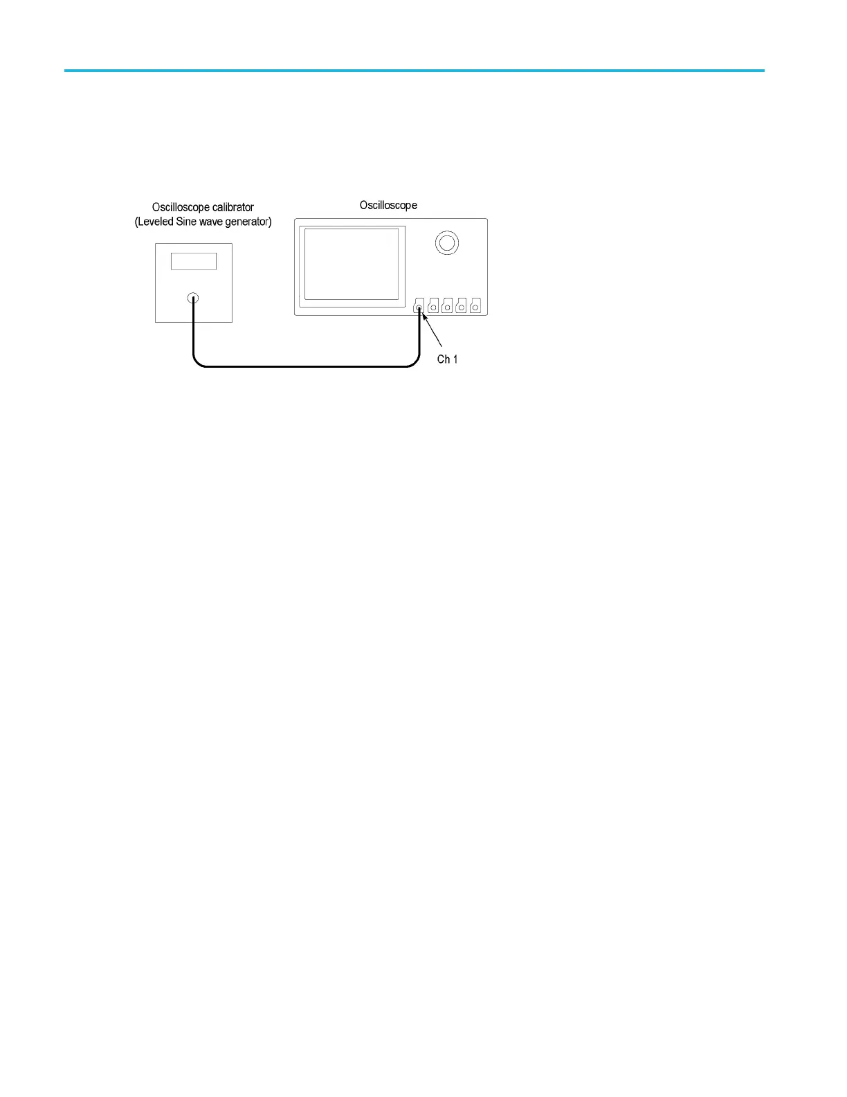
Check DVM Voltage Accuracy (AC)
This test ch ecks the DVM voltage accurac y (AC).
1. Connect the output of the leveled sine wave generator (for example, Fluke 9500) to the oscilloscope channel 1 input as
shown below.
2. Push Defa
ult Setup on the front panel to set the instrument to the factory default settings.
3. Push chan
nel button 1, 2, 3,or4 for the channel that you want to check.
4. Set the ge
nerator to 50 output impedance (50 source impedance).
5. Set the o
scilloscope termination to 50 . Push Termin ation on the lower menu to select 50 Ω.
6. Set the g
enerator to produce a square wave of the amplitude and frequency listed in the test record (for example,
20 mV
pp
and1kHz).
7. Turn the vertical scale knob so that the signal covers between 4 and 8 vertical divisions on screen.
8. Push the Measure button, then the DVM lower-bezel button to turn on the DVM function.
9. Use the multipurpose knob a to select AC RMS mode
10. Use the multipurpose knob b to select the input channel being tested.
11. Enter the measured value in the test record.
12. Repeat procedure for each voltage and frequency combination shown in the record.
13. Repeat all steps for each oscilloscope channel.
This completes the procedure.
116 MDO3000 Series Specifications and Performance Verification

 Loading...


