Performance Ver
ification
Check L ong-term Sample Rate and Delay Time Accuracy
This test checks the sample rate and delay time accuracy (time base).
1. Push Default Setup on the oscilloscope front panel to set the instrument to the factory default s ettings.
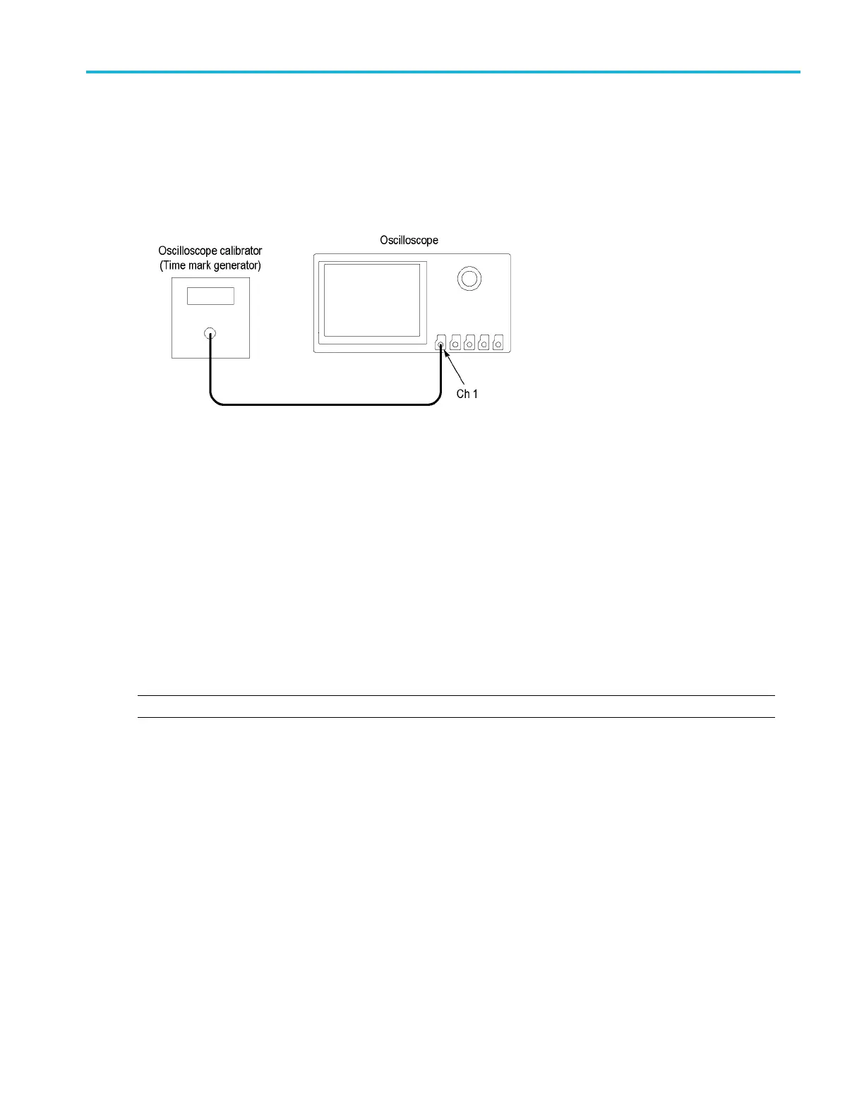
2. Connect the output of the time mark generator to the oscilloscope channel 1 input using a 50 cable. Use the time mark
generator with a 50 source with the oscilloscope set for internal 50 termination.
3. Set the time mark generator to 80 ms. Use a time mark waveform with a fast rising edge.
4. Set the mark amplitude to 1 V
pp
.
5. Set the oscilloscope vertical Scale to 500 mV/div.
6. Set the Horizontal Scale to 20 ms/div.
7. Adjust the Trigger Level for a triggered display.
8. Adjust the vertical Position knob to center the time mark on center screen.
9. Adjust the Horizontal Position knob counterclockwise to set the delay to exactly 80 ms.
10. Set the Horizontal Scale to 400 ns/div.
11. Compare the rising edge of the m arker to the center horizontal graticule. The rising edge should be w ithin ±2 divisions of
the ce
nter graticule. Enter the deviation in the test record. (S ee page 49, Sample Rate and Delay Time Accuracy.)
NOTE. One division of displacement from graticule center corresponds to a 5 ppm time base error.
This completes the procedure.
MDO3000 Series S pecifications and Performance Verification 85

 Loading...


