Performance Ve ri fi cation
Check Analog Bandwidth
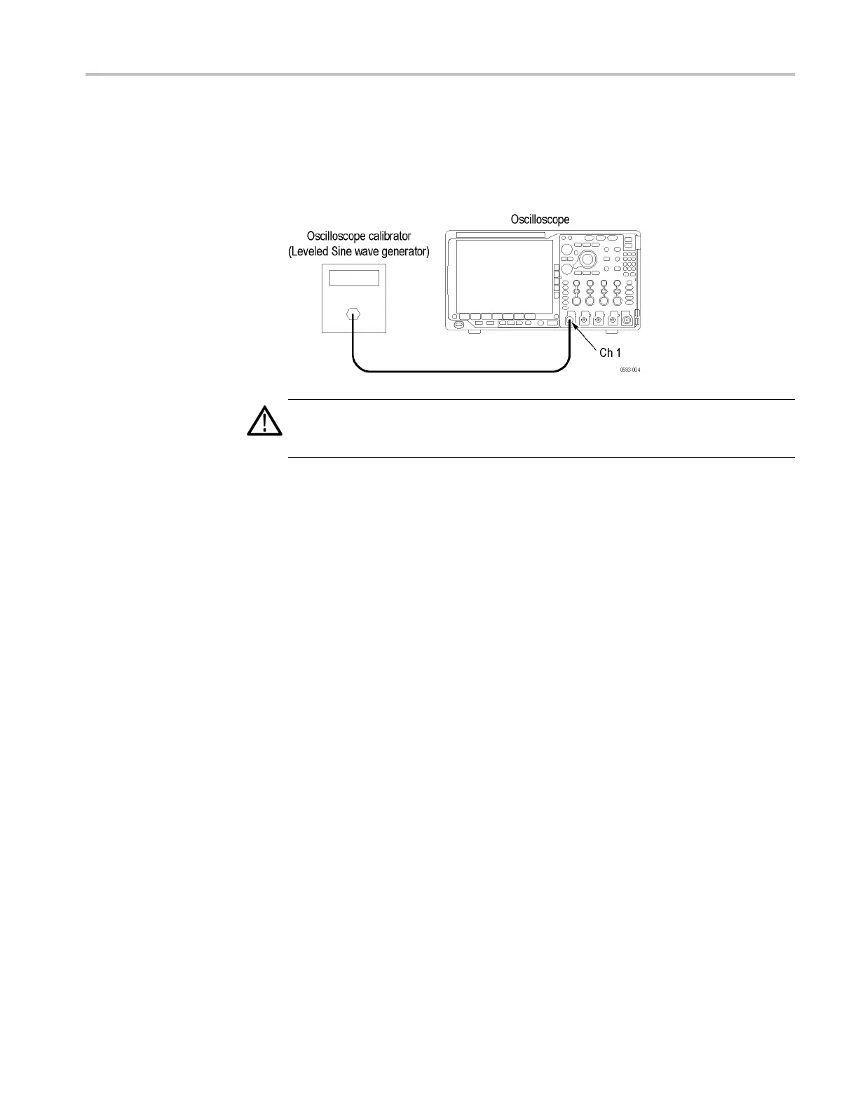
This test check
s the bandwidth at 50 Ω and 1 M Ω for each channel.
1. Connect the output of the leveled sine wave generator (for example, Fluke
9500) to the os
cilloscope channel 1 input as shown in the following
illustration.
WARNING. The generator is capable of providing dangerous voltages. Be sure to
set the generator to off or 0 volts before connecting, disconnecting, and/or moving
the test hookup during the performance of this procedure.
2. Push the front-panel Default Setup button.
3. Select 50 Ω impedance as follows:
a. Set the calibrator to 50 Ω output impedance and to generate a sine wave.
b. Push the front-panel channel 1 button.
c. Set t
he Termination (input impedance) to 50 Ω.
4. Set the Acquisition mode to Sample as follows:
a. Push the front-panel Acquire button.
b. Push the Mode lower-bezel button (if not already selected).
c. Push the Sample side bezel button.
5. Set the Vertical Scale to 1mVper d ivision.
6
.
F
or vertical scales less than 500 mV/div, adjust the signal source to at least
8 vertical divisions at the selected vertical scale with a set frequency of
50 kHz. For example, at 5 mV/div, use a ≥40 mV
p-p
signal, at 2 mV/div, use a
≥16 mV
p-p
signal, and at 1 mV/div, use a ≥8mV
p-p
signal. For vertical scales
of 500 mV/div and 1 V/div adjust the signal source to 3 V
p-p
.Useasinewave
for the signal source.
7. Set the Horizontal Scale to 10 μs per division.
MDO4000 Series Specifications and Performance Verification 73
 Loading...


