Performance Verification
Check Digital Threshold
Accuracy
This test check
s the threshold accuracy of the digital channels. This procedure
applies to digital channels D0 through D15, and to channel threshold values of
0Vand+4V.
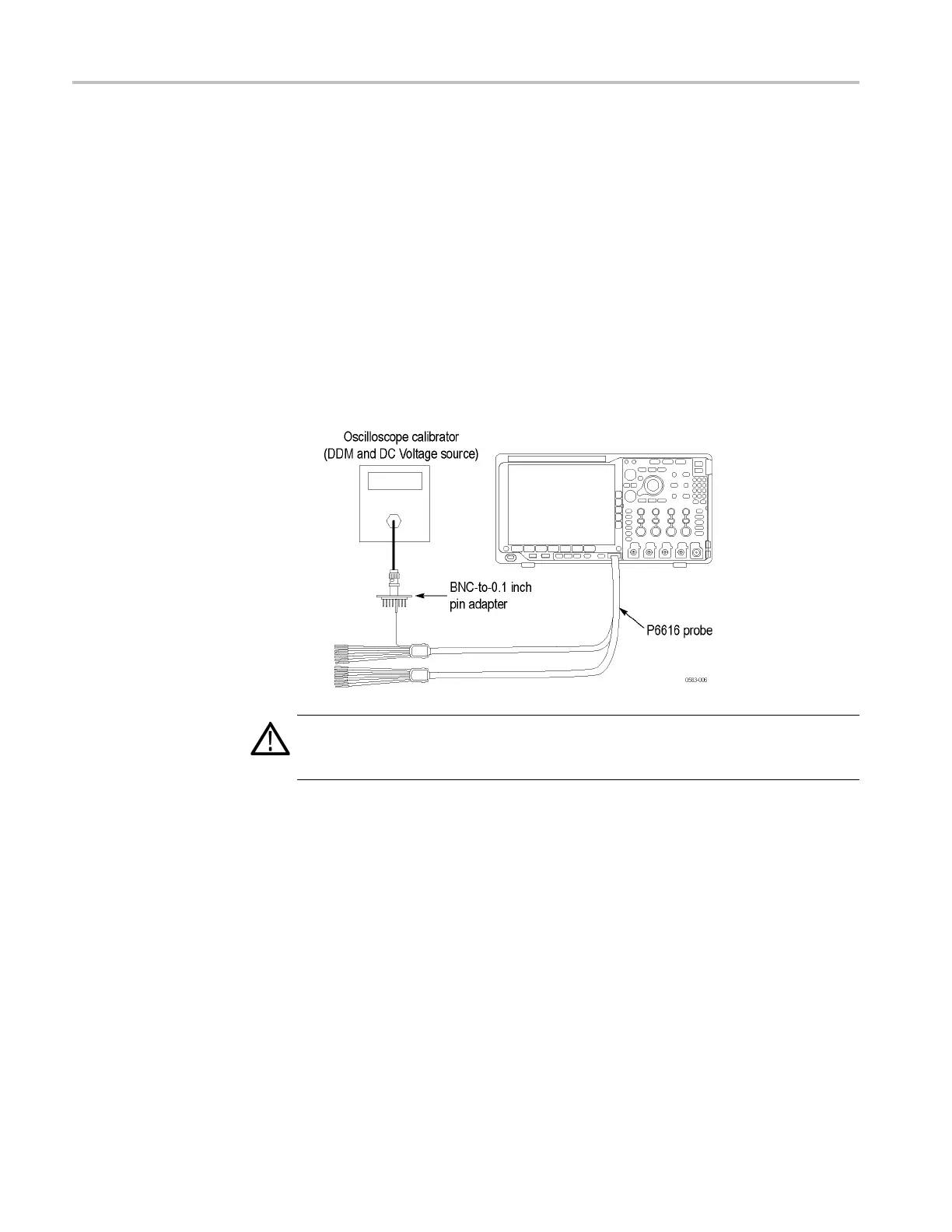
1. Connect the P6616 digital probe to the oscilloscope, as shown in the following
illustration:
a. Connect the DC voltage source to the digital channel D0.
b. If you are us
ing the Fluke 9500 calibrator as the DC voltage source,
connect the calibrator head to the d igital channel D0, using the
BNC-to-0.1 inch pin adapter listed in the Required Equipment table. (See
Table 15 on page 28.)
c. Connect channel D0 to both the corresponding signal pin and to a ground
pin on the adapter.
WARNING. The generator is capable of providing dangerous voltages. Be sure to
set the generator to off or 0 volts before connecting, disconnecting, and/or moving
the test hookup during the performance of this procedure.
2. Turn on the digital channels as follows:
a. Push the front-panel D15-D0 button.
b. Push the D15-D0 On/Off lower-bezel button.
c. Push the Turn On D7 - D0 and the Turn On D15 - D8 side-bezel buttons
to turn these channels On.
d. Make sure that the side-bezel Display selection is On.
e. The instrument will display the 16 digital channels.
82 MDO4000 Series Specifications and Performance Verification
 Loading...


