Display Wavefor
mData
Quick Tips
Preview. If you change the Position or Scale controls when the acquisition is stopped or when it is waiting for the next
trigger, the oscilloscope rescales and repositions the relevant waveforms in response to the new control settings. It
simulates what you w ill see when you next push the RUN button. The o scilloscope uses the new settings for the next
acquisition.
You may see a clipped waveform if the ori ginal acquisition went off the screen.
The math waveform, cursors, and automatic measurem ents remain active and valid when using preview.
Setting Input Parameters
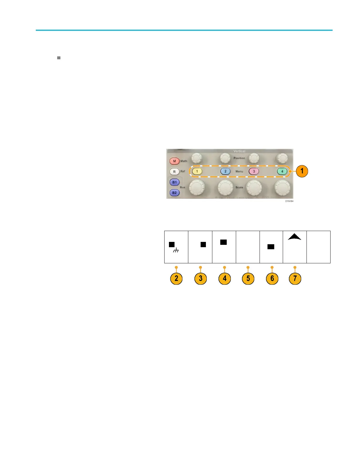
Use the vertical controls to select waveforms, adjust the waveform vertical position and scale, and set input parameters.
1. Push a channel menu button 1, 2, 3,or4 to
bring up the vertical menu for the designated
waveform. The vertical menu only affects
the selected waveform.
Pushing a channel button will also select or
cancel that waveform selection.
2. Push Coupling repeatedly to select the
coupling to use.
Use DC coupling to pass both AC and DC
components.
Coupling
DC|AC
Invert
On |
Off
Bandwidth
Full
(1) Label (1) Probe
Setup
10X
More
Use AC coupling to block the DC component
and show only the AC signal.
Use Ground (GND) to display the reference
potential.
3. Push Invert to invert the signal.
Select Off for normal operation and On
to invert the polarity of the signal in the
preamplifier.
4. Push Bandwidth, and select the desired
bandwidth from the resulting side-bezel
menu.
The default choices are Full and 20 MHz.
Additional choices may appear, depending
on the probe that you use.
Select Fu ll to set the bandwidth to the full
oscilloscope bandwidth.
Select 20 MHz to set the bandwidth to
20 MHz.
MSO2000B and DPO2000B Series Oscilloscopes User Manual 81

 Loading...