Trigger Setup
Selecting Triggers
Trigger type Trigger conditions
Edge
Trigger on a rising or falling edge, as defined by the
slope control. Coupling choices are DC, LF Reject, HF
Reject, and N
oise Reject.
Edge triggers are the simplest and most commonly
used trigger type, with both analog and digital signals.
An edge trigg
er event occurs when the trigger source
passes through a s pecified voltage level in the specified
direction.
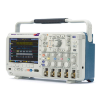
Pulse Width Trigger on pulses that are less than, greater than, equal
to, or not equal to a specified time. You can trigger on
positive o
r negative pulses. Pulse width triggers are
primarily used on digital s ignals.
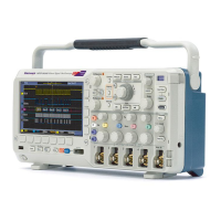
Runt Trigger on a pulse amplitude that crosses one threshold
but fails
to cross a second threshold before recrossing
the first. You can detect positive or negative (or either)
runts, or only those wider than, less than, greater than,
equal to
, or not equal to a specified width. Runt triggers
are primarily used on digital signals.
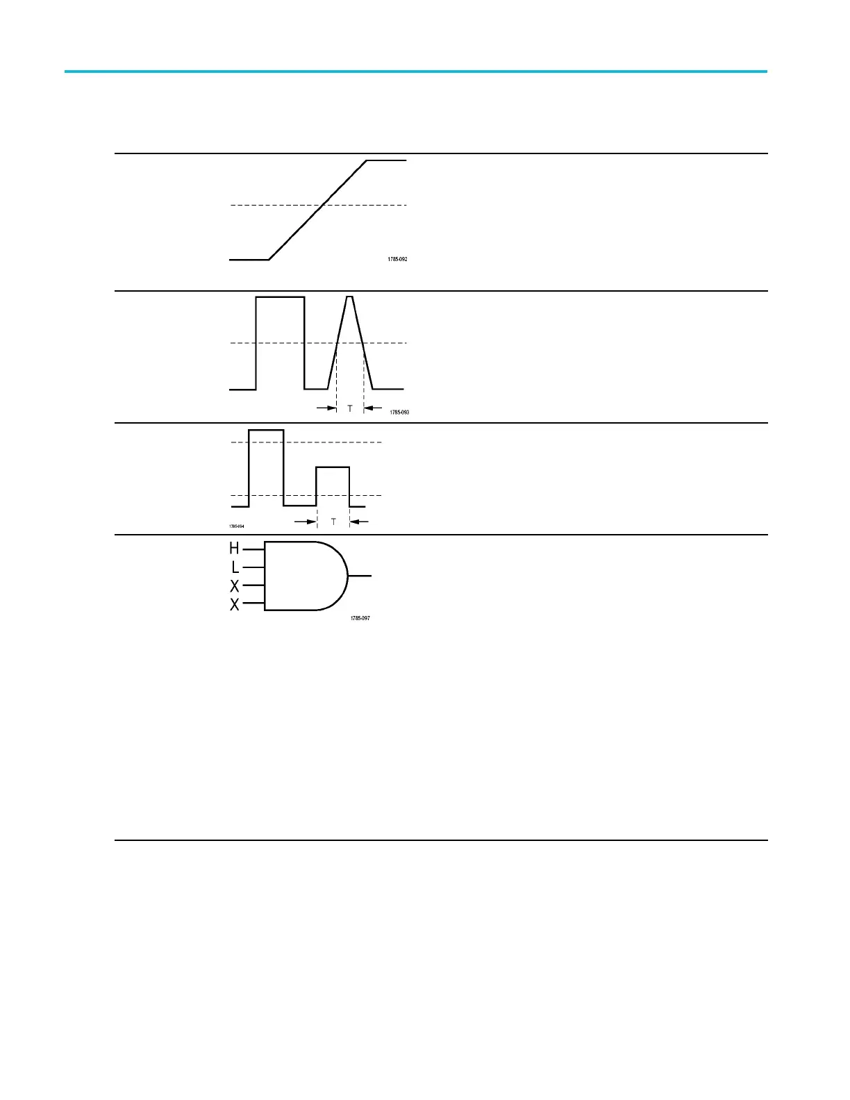
Logic
Trigger when all channels transition to the specified
state. Use multipurpose knob a to select a channel.
Push the appropriate side-bezel button to set that
channel's state to High (H), Lo w (L) ,orDon't Care (X).
Use the Cloc k side-bezel button to enable clocked
(state) triggering. You can have at most a single clock
channel. Push the Clock E dge bottom bezel button to
change the polarity of the clock edge. Turn off clocked
triggering and return to unclocked (pattern) triggering by
selecting the clock channel and setting it to high, low,
or don't care.
For unclocked triggering, by default, triggering occurs
when the selected condition goes true. You can also
select triggering when the condition goes false, or
time-qualified triggering.
You can use up to 20 channels for a logic trigger
(4 analog and 16 digital) with MSO2000B series
oscilloscopes.
68 MSO2000B and DPO2000B Series Oscilloscopes User Manual

 Loading...