Getting Acquain
ted with the Oscilloscope
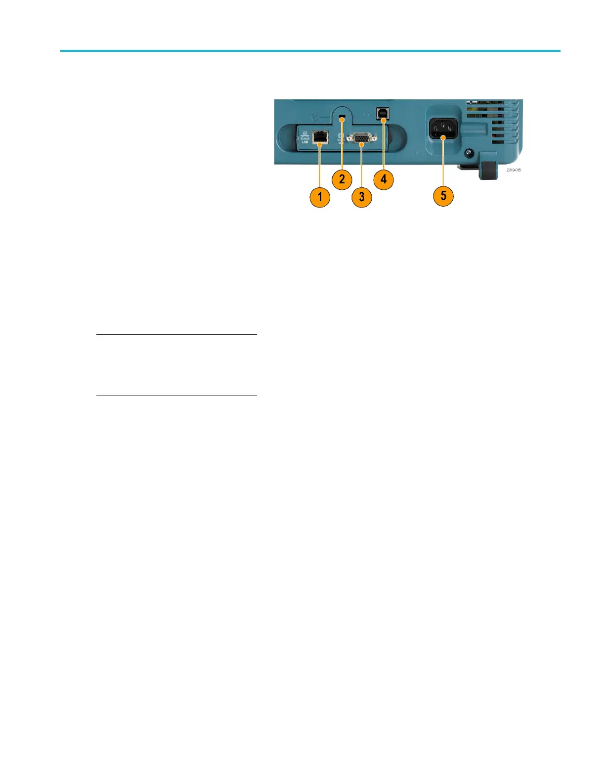
Rear-Panel Connectors
1. LAN.UsetheLA
N (Ethernet) port (RJ-45
connector) to connect the oscilloscope
to a 10/100 Base-T local area network.
The port is ava
ilable on the optional
connectivity module (DPO2CONN).
2. Lock. Use to secure the oscilloscope
and optional connectivitiy module.
3. Video Out. Use the Video Out port
(DB-15 fema
le connector) to show the
oscilloscope display on an external
monitor or projector. The port is available
on the opti
onal connectivity module
(DPO2CONN).
4. USB 2.0 Device port.UsetheUSB
2.0 Full Speed Device port to connect
aPictBri
dge compatible printer, or for
direct PC control of the oscilloscope
using USBTMC protocol.
NOTE. Th
e cable connected from the USB
2.0 Device port to the host computer must
meet the USB2.0 specification for high speed
operati
on when connected to a high speed
host c ontroller.
5. Power input. Attach to an AC power line
with i
ntegral safety ground. (See page 5,
Operating C onsiderations .)
MSO2000B and DPO2000B Series Oscilloscopes User Manual 39

 Loading...