Getting Acquain
ted with the Oscilloscope
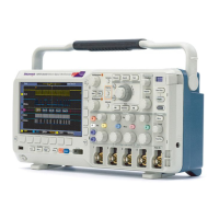
14. For digital channels (MSO2000B series
only), the baseline indicators label the
channel, and p
oint to the high and low
levels. The colors follow the color code
used on resistors. The D0 indicator is
black, the D1
indicator is brown, the
D2 indicator is red, and so on.
The bus display s hows decoded packet
level inform
ation for serial buses or for
parallel buses (MSO2000B series only).
The bus indicator shows the bus number
and bus type
.
Not shown in this illustration, the Timing
Resolutio
n readout shows the timing
resolution of the digital channels. To see
the readout, push the D15-D0 front panel
button.
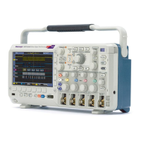
15. For math c
hannels, the waveform
baseline indicator shows the zero-volt
level of a waveform.
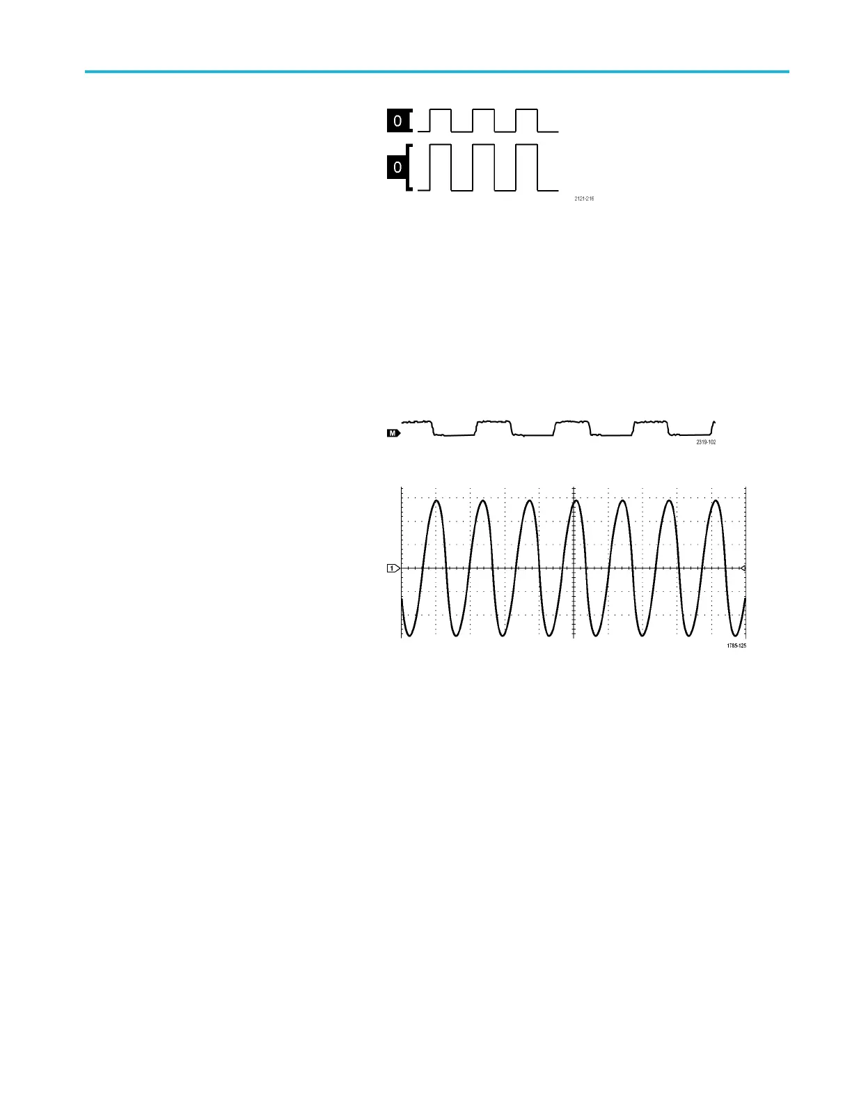
16. For analog channels, the waveform
baseli
ne indicator shows the zero-volt
level of a waveform (ignoring the effect
of offset). The icon colors correspond to
the wav
eform colors.
MSO2000B and DPO2000B Series Oscilloscopes User Manual 37

 Loading...