Application Exa
mples
Tracking Down Bus Anomalies
In this example, you are testing your new I
2
C circuit. Something is not working. You tell the master IC to send a message
to the slave IC. Then you expect to receive data back and an LED to light. The light never goes on. Where in the ten o r
so commands that were sent out did the problem occur? Once you locate the problem location, how do you determine
what went wrong?
You can use your oscilloscope, with its serial triggering and long-record length management features, to track down the
problem in both the physical layer and in the protocol layer of the bus.
Basic S trategy
First, you will d isplay and acquire the bus signal by setting up the bus parameters and trigger. Then, you will search through
each packe
t w ith the search/mark functions.
NOTE. Triggering on I
2
C, SPI, USB, CAN, LIN, FlexRay, RS-232, RS-422, RS-485, UART, I
2
S, Left Justified, Right Justified,
TDM, MIL-STD-1553, and Ethernet bus signals requires use of an appropriate DPO4EMBD, DPO4USB, DPO4AUTO,
DPO4AUTOM
AX, DPO4COMP, DPO4AUDIO, DPO4AERO, and DPO4ENET Serial Triggering and Analysis Module.
Triggering on Parallel bus signals requires an MSO4000B Series oscilloscope.
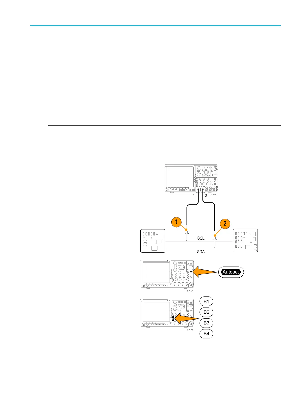
1. Connect the channel 1 probe to the clock
line.
2. Connect the channel 2 probe to the data
line.
3. Push Autoset.
4. Push the B1 button and enter the parameters
of your I
2
C bus in the resulting screen
menus.
MSO4000B and DP O4000B Series Oscilloscopes User Manual 181

 Loading...


