Acquire the Sign
al
For example, an RS-232 signal (after the start bit) might be high, high, high, low, high, low, low, and high. Since the RS-232
protocol uses h
igh for zero and low for one, this value would be 0001 0110.
Since the deco
de displays the MSB fi rst, the oscilloscope reverses the order of the bits and displays 0110 1000. If the bus
display is set to hex, the value displays as 68. If the bus display is set to AS CII, the value displays as h.
Setting Up Digital Channels
Use front panel buttons and knobs to set up your instrument to acquire signals using the digital channels.
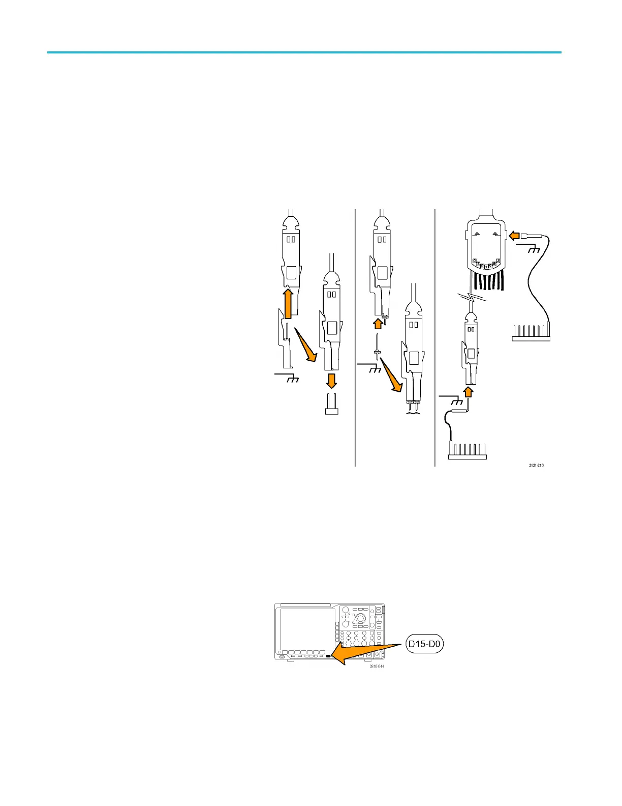
1. Connect the
P6616 16-channel logic probe
to the input signal source.
2. Connect the ground lead or leads to the
circuit ground.
You can connect a separate lead for each
channel or a common ground lead for each
group of 8 wires.
3. If needed, connect the appropriate grabber
for each p robe to the probe tip.
4. Connect the each probe to the desired circuit
test point.
5. Push the D15 - D0 front panel button to
display the menu.
72 MSO4000B and DPO 4000B Series Oscilloscopes User Manual

 Loading...


