Performance ver
ification
Input-related spurious resp onse: first converter images
NOTE. Youdono
t need to do the first three steps (setup, reset, and alignment) when you perform the input-related spurious
response tests in sequence.
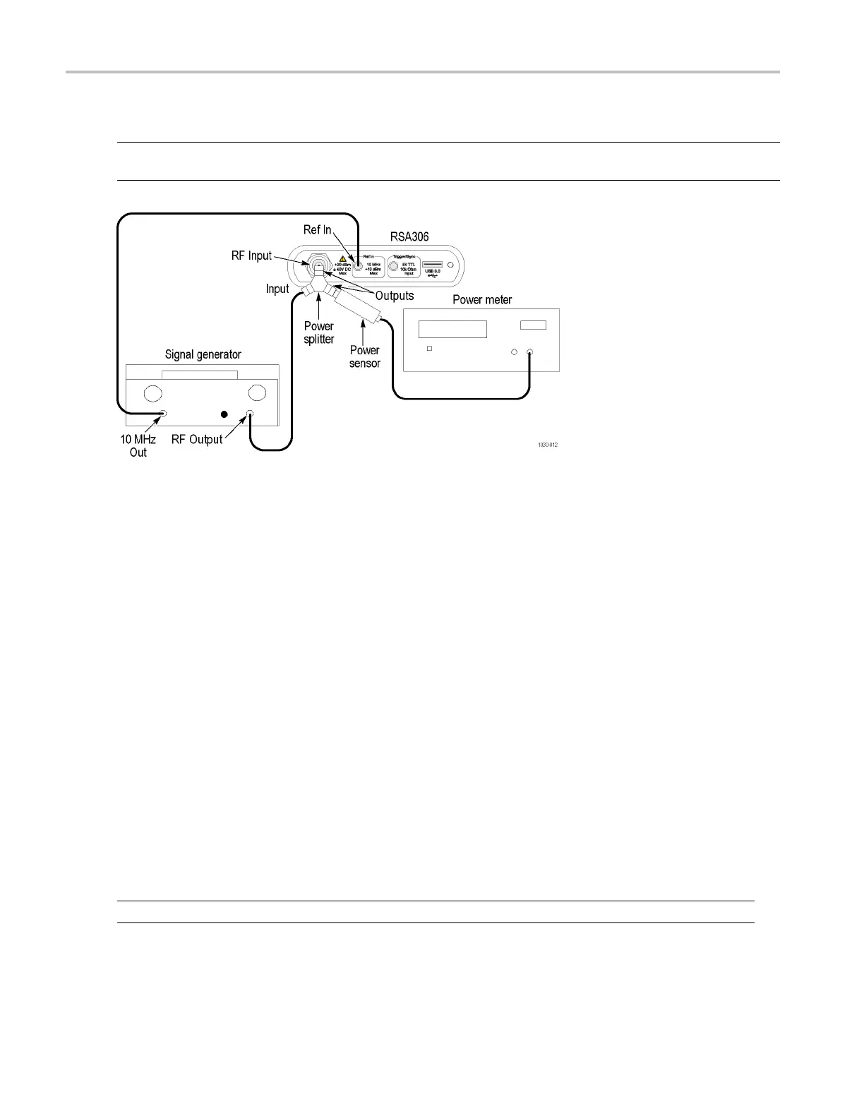
1. Connect the signal generator, power splitter, power sensor, power meter, and RSA306 as shown. Connect the power
sensor and RF signal generator directly to the power splitter, which is connected directly to the RSA306.
2. Reset the RSA306 to factory defaults (Presets > Main).
3. Run the RSA 306 alignment procedure (Tools > A lignments > Align Now).
4. Set the RSA306 as follows:
a. Reference Level = –30 dBm
b. Span = 1MHz
c. RBW = 1kHz
d. Detection mode = +PEAK (Setup > Settings > Traces > Detection > +PEAK)
e. Function = Avg (Vrms) (Setup > Settings > Traces > Function)
f. Averaging = 10 (Setup > Settings > Traces > Function; count = 10)
g. Select External Reference (Setup > Acquire > Frequency Reference > External)
5. Set the signal generator output for –30 dBm at the power meter and RSA306 input.
6. Set the RSA306 to the Center frequency shown in the First converter images table. (See Table 18 on page 42.)
7. Set the signal generator frequency to the Image frequency value in the
table.
NOTE. Monitor and set the signal generator amplitude to –30 dBm whenever you change frequency settings during this test.
8. Measure and record the Image Amplitude at the RSA306 CF.
41 RSA306 Speci fications and Performance Verification

 Loading...


