Performance ver
ification
Amplitude accuracy at all center frequencies
Amplitude accuracy is tested for four different reference levels which exercises the different RF gain conditions used in
the RSA306.
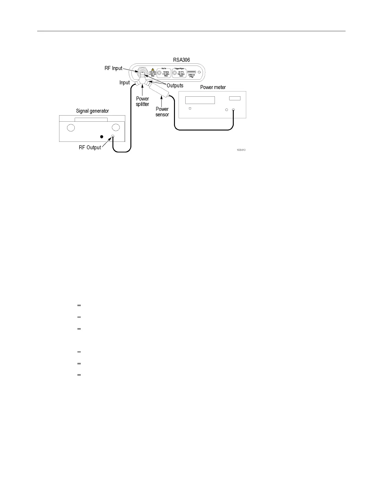
1. Connect the signal generator, power splitter, power sensor, power meter, and RSA306 as shown. Connect the power
sensor and RF signal generator directly to the power splitter, which is connected directly to the RSA306.
2. Reset the RSA306 to factory defaults (Presets > Main).
3. Run the RSA306 alignment procedure (Tools > Alignments > Align Now).
4. Set the RSA306 as follows:
a. Reference Level = +20 dBm
b. Detection = +PEAK (S etup > Settings > Traces > Detection > +PEAK)
c. Filter shape = Flat-Top (Setup > Settings > BW > Filter Shape > Flat-top)
d. Center Frequency: as listed in the amplitude accuracy tables. (See Table 5.) (See Table 6.) (See Table 7.) (See
Table 8.)
e. Span:
For CF < 1 MHz, Span = 100 kHz
For 1 MHz CF 30 MHz, Span = 1 MHz
For C F 30 MHz, Span = 10 MHz
d. RBW:
For C F < 1 MHz, RBW = 1 kHz
For 1 MHz CF 30 MHz, RBW = 10 kHz
For CF > 30 MHz, RBW = 100 kHz
5. Set the signal generator output amplitude to +12 dBm. The RF amplitude at the power sensor and RSA306 input
= +6 dB m nominal.
6. Set the signal generator frequency to the first frequency in the +20 dBm reference level accuracy table. (See Table 5.)
7. Set the RSA306 center frequency to the same frequency. (See Table 5.)
RSA306 Specifications and Performance Verification 16

 Loading...


