Maintenance
TDS1000 and TDS2000 Series Digital Storage Oscilloscopes Service Manual
6-- 23
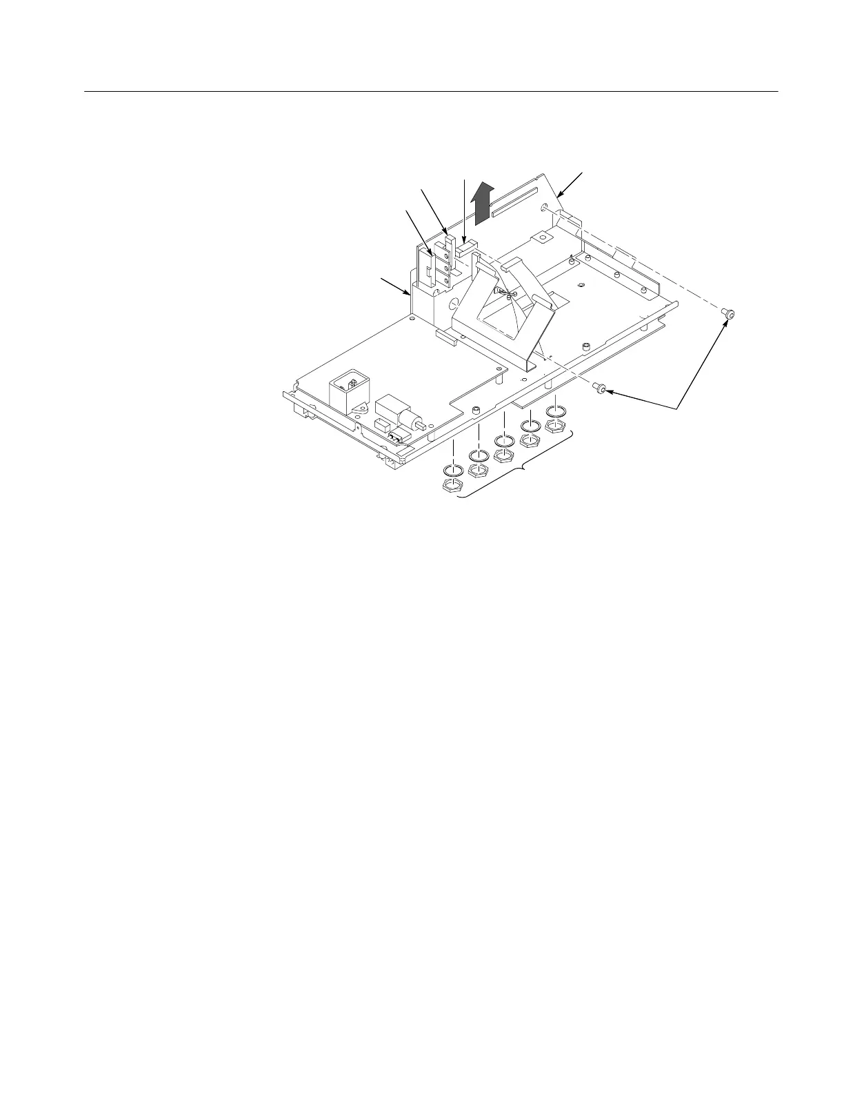
Remove Main board
screws (2)
Front-panel connector
Display connector
Power supply connector
Main board module
Internal assembly
Remove hex nuts and lock washers
Figure 6--13: Main board removal
Installation. To install the main board module, refer to Figure 6--13 and follow
these steps:
1. Working from the bottom of the internal assembly, place the front of the
main board module into the slots on the assembly (near the the BNC
connectors).
2. Use the deep socket to attach the washers and nuts to each BNC connector so
that the main board is securely attached to the chassis. Torque the nuts to 40
in-lbs using the torque wrench.
3. Install the two screws attaching the main board module to the internal
assembly.
4. Reconnect the following wires on the main board:
H The power supply ribbon cable at J101.
H The display cable at J201.
H The front-panel cable at J202.
5. Use the installation procedure for each module removed to reassemble the
oscilloscope.

 Loading...

