Maintenance
6-- 16
TDS1000 and TDS2000 Series Digital Storage Oscilloscopes Service Manual
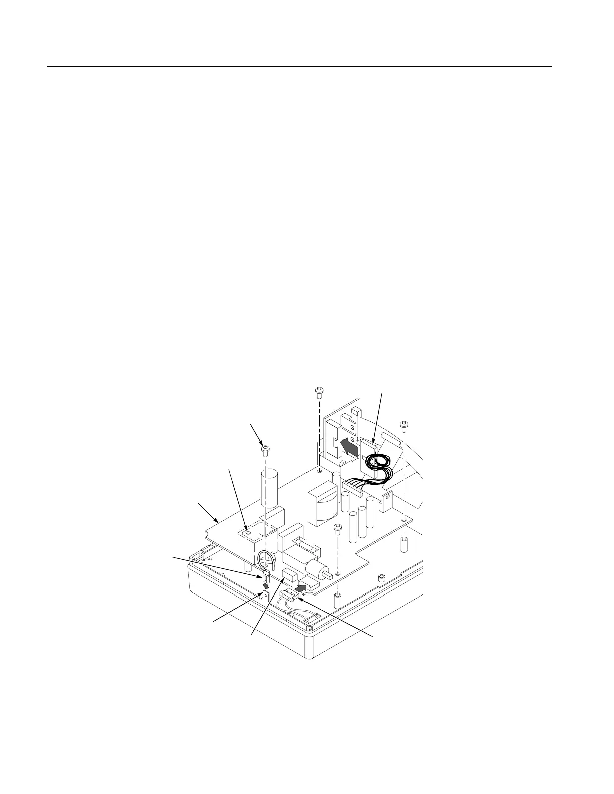
Installation. To install the power supply module, refer to Figure 6--8 and follow
these steps:
1. Align and place the power supply module into the internal assembly.
2. Install the four screws. Do not put a screw into the empty hole in Figure 6--8.
3. Reconnect the following wires:
H The ground wire on the power supply module to the chassis ground lug.
You may need to use pliers to secure the wire in place.
H The two-conductor backlight cable on the power supply module.
Connect to the black socket for a monochrome LCD, and to the white
socket for a color LCD.
H The power supply ribbon cable to the main board at J101. Twist the cable
four revolutions to keep it from contact with the boards and chassis.
4. Use the installation procedure for each module removed to reassemble the
oscilloscope.
Install screws (4)
Power supply ground wire
Backlight cable
(color LCD)
Power supply
ribbon cable
Backlight connector
(monochrome LCD)
Power supply module
Chassis ground lug
Empty hole
NO SCREW
Figure 6--8: Installing the power supply module

 Loading...

