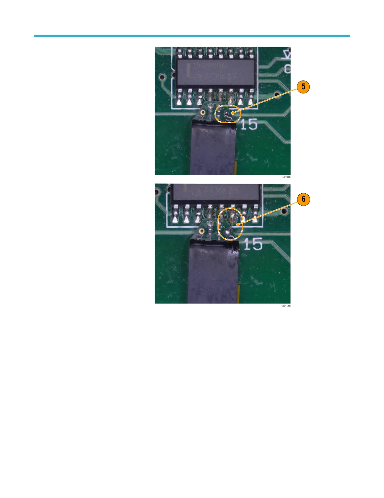
Attach the ground wire for
TriMode input to the probe tip.
First add solder to the test point
and the nearest ground via on the
solder tip.
Second, solder a short piece of
wire between the ground via on
the tip and the ground test point.
This configuration optimizes the
performance of the probe for
differential measurements.
Longer wires on the ground path
will have an impact on Single-
Ended Mode and Common Mode
performance. If there is a ground
test point conveniently placed, it
would be best to use the same
solder technique shown on the A
and B inputs of the tip to ensure
the shortest ground path. Once
the tip is fully soldered in place, it
is recommended to firmly secure
the tip to the board using
additional foam tape or hot melt
glue.
Basic operation
P7700 Series TriMode™ Probes 32

 Loading...


