7 Specifications
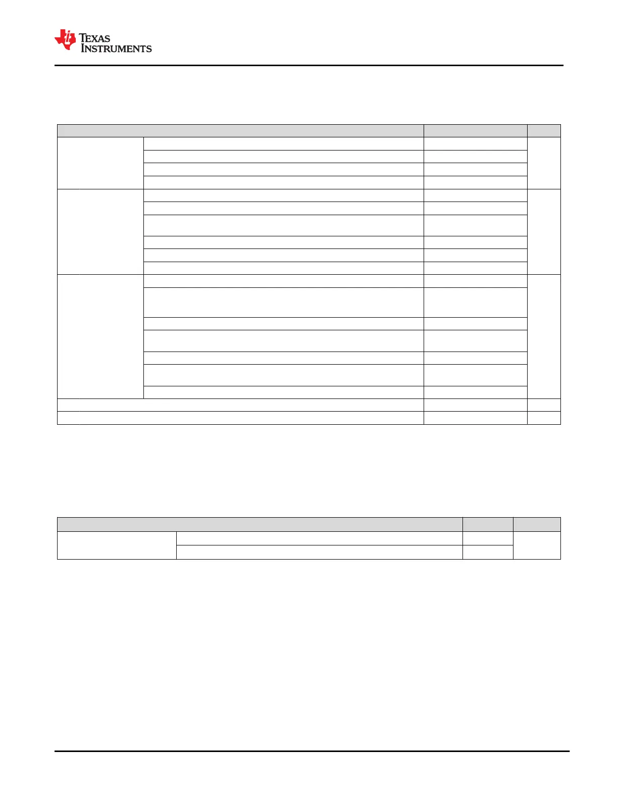
7.1 Absolute Maximum Ratings
over operating free-air temperature range (unless otherwise noted)
(1)
MIN MAX UNIT
V
I
Input voltage
(2)
PP_CABLE, PP_5V0 –0.3 6
V
VIN_3V3 –0.3 3.6
SENSEP
(3)
, SENSEN
(3)
–0.3 24
VDDIO, UART_RX –0.3 LDO_3V3 + 0.3
V
IO
Output voltage
(2)
LDO_1V8A, LDO_1V8D, LDO_BMC, SS –0.3 2
V
LDO_3V3 –0.3 3.45
VOUT_3V3, RESETZ, I2C _IRQ1Z, I2C_IRQ2Z, SPI_PICO, SPI_CLK, SPI_CSZ,
LSX_P2R, SWD_CLK, UART_TX
–0.3 LDO_3V3 + 0.3
HV_GATE1, HV_GATE2 –0.3 30
HV_GATE1 (relative to SENSEP), –0.3 6
HV_GATE2 (relative to VBUS)
V
IO
I/O voltage
(2)
PP_HV, VBUS
(3)
–0.3 24
V
I2C_SDA1, I2C_SCL1, SWD_DATA, SPI_POCI, I2C_SDA2, I2C_SCL2, LSX_R2P,
USB_RP_P, USB_RP_N, AUX_N, AUX_P, DEBUG1, DEBUG2, DEBUG3, DEBUG4,
DEBUG_CTL1, DEBUG_CTL2, GPIOn, MRESET, BUSPOWERZ, GPIO0-8
–0.3 LDO_3V3 + 0.3
R_OSC, I2C_ADDR –0.3 2
HRESET –0.3
LDO_1V8D +
0.3
C_USB_TP, C_USB_TN, C_USB_BP, C_USB_BN, C_SBU2, C_SBU1 (switches open) –2 6
C_USB_TP, C_USB_TN, C_USB_BP, C_USB_BN, C_SBU2, C_SBU1 (switches
closed)
–0.3 6
C_CC1, C_CC2, RPD_G1, RPD_G2 –0.3 6
T
J
Operating junction temperature –10 125 °C
T
stg
Storage temperature –55 150 °C
(1) Stresses beyond those listed under Absolute Maximum Ratings may cause permanent damage to the device. These are stress
ratings only, which do not imply functional operation of the device at these or any other conditions beyond those indicated under
Recommended Operating Conditions. Exposure to absolute-maximum-rated conditions for extended periods may affect device
reliability.
(2) All voltage values are with respect to network GND. All GND pins must be connected directly to the GND plane of the board.
(3) The 24-V maximum is based on keeping HV_GATE1/2 at or below 30 V. Fast voltage transitions (< 100 ns) may occur up to 30 V.
7.2 ESD Ratings
VALUE UNIT
V
(ESD)
Electrostatic
discharge
Human-body model (HBM), per ANSI/ESDA/JEDEC JS-001
(1)
±1500
V
Charged-device model (CDM), per JEDEC specification JESD22-C101
(2)
±500
(1) JEDEC document JEP155 states that 500-V HBM allows safe manufacturing with a standard ESD control process. Manufacturing with
less than 500-V HBM is possible with the necessary precautions.
(2) JEDEC document JEP157 states that 250-V CDM allows safe manufacturing with a standard ESD control process. Manufacturing with
less than 250-V CDM is possible with the necessary precautions.
www.ti.com
TPS65982
SLVSD02E – MARCH 2015 – REVISED AUGUST 2021
Copyright © 2021 Texas Instruments Incorporated
Submit Document Feedback
11
Product Folder Links: TPS65982

 Loading...


