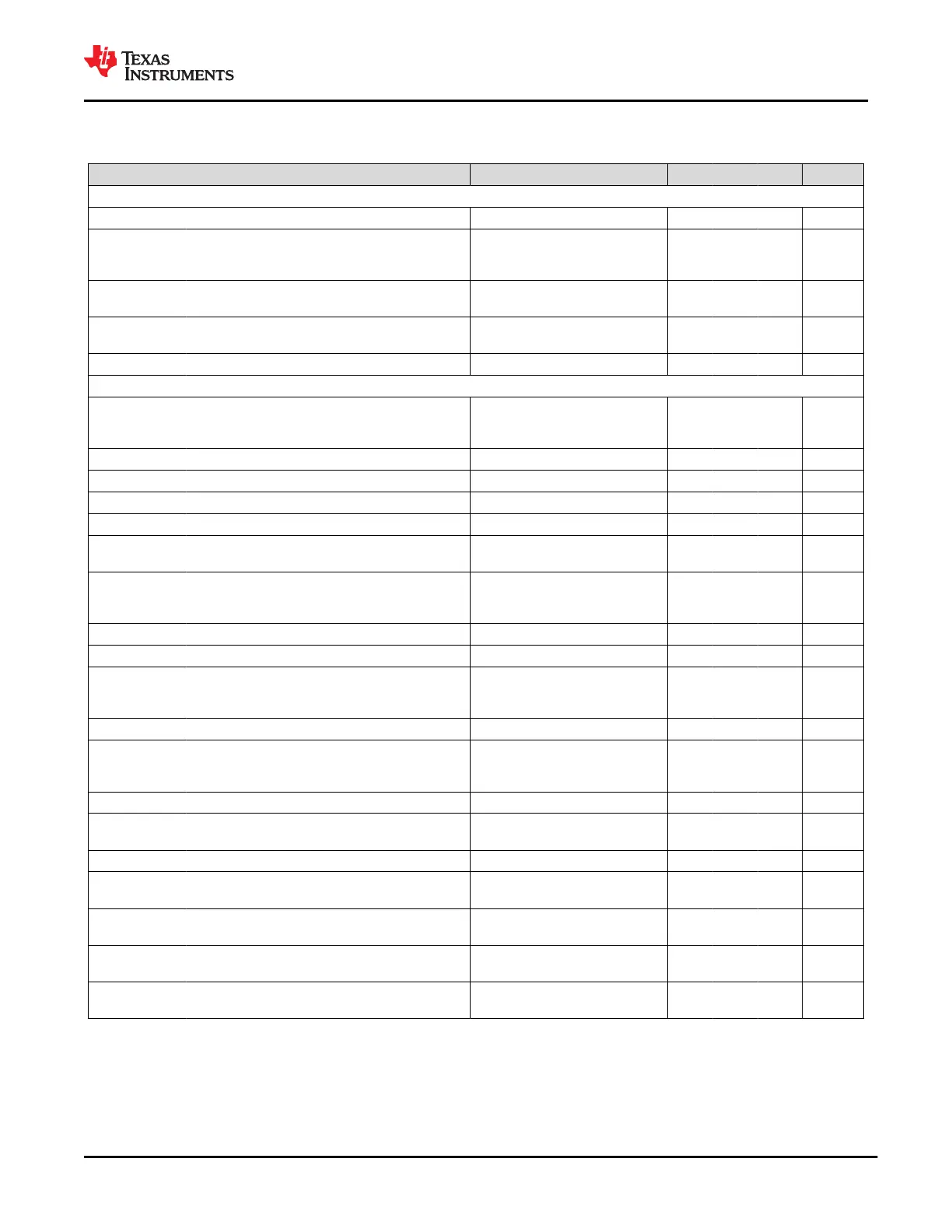
7.5 Power Supply Requirements and Characteristics
Recommended operating conditions; T
A
= –10 to 85°C unless otherwise noted
PARAMETER TEST CONDITIONS MIN TYP MAX UNIT
EXTERNAL
VIN_3V3 Input 3.3-V supply 2.85 3.3 3.45 V
PP_CABLE
Input voltage to power C_CC pins. This input
is also available to power core circuitry and the
VOUT_3V3 output
2.95 5 5.5 V
VBUS
Bi-direction DC bus voltage. Output from the
TPS65982 or input to the TPS65982
4 5 22 V
PP_5V0
5V supply input to power VBUS. This supply does
not power the TPS65982
4.75 5 5.5 V
VDDIO
(1)
Optional supply for I/O cells 1.7 3.45 V
INTERNAL
VLDO_3V3
DC 3.3V generated internally by either a switch
from VIN_3V3, an LDO from PP_CABLE, or an
LDO from VBUS
2.7 3.3 3.45 V
VDO_LDO3V3 Drop Out Voltage of LDO_3V3 from PP_CABLE I
LOAD
= 50 mA 250 mV
Drop Out Voltage of LDO_3V3 from VBUS 250 500 750 mV
VLDO_1V8D DC 1.8V generated for internal digital circuitry 1.7 1.8 1.9 V
VLDO_1V8A DC 1.8V generated for internal analog circuitry 1.7 1.8 1.9 V
VLDO_BMC
DC voltage generated on LDO_BMC. Setting for
USB-PD
1.05 1.125 1.2 V
ILDO_3V3
DC current supplied by the 3.3V LDOs. This
includes internal core power and external load on
LDO_3V3
70 mA
ILDO_3V3EX External DC current supplied by LDO_3V3 30 mA
IOUT_3V3 External DC current supplied by VOUT_3V3 100 mA
ILDO_1V8D
DC current supplied by LDO_1V8D. This is
intended for internal loads only but small external
loads may be added
50 mA
ILDO_1V8DEX External DC current supplied by LDO_1V8D 5 mA
ILDO_1V8A
DC current supplied by LDO_1V8A. This is
intended for internal loads only but small external
loads may be added
20 mA
ILDO_1V8AEX External DC current supplied by LDO_1V8A 5 mA
ILDO_BMC
DC current supplied by LDO_BMC. This is
intended for internal loads only
5 mA
ILDO_BMCEX External DC current supplied by LDO_BMC 0 mA
VFWD_DROP
Forward voltage drop across VIN_3V3 to
LDO_3V3 switch
I
LOAD
= 50 mA 25 60 90 mV
RIN_3V3
Input switch resistance from VIN_3V3 to
LDO_3V3
V
VIN_3V3
– V
LDO_3V3
> 50 mV 0.5 1.1 1.75 Ω
ROUT_3V3
Output switch resistance from VIN_3V3 to
VOUT_3V3
0.35 0.7 Ω
TR_OUT3V3
10-90% rise time on VOUT_3V3 from switch
enable
C
VOUT_3V3
= 1 μF 35 120 µs
(1) I/O buffers are not fail-safe to LDO_3V3. Therefore, VDDIO may power-up before LDO_3V3. When VDDIO powers up before
LDO_3V3, the I/Os shall not be driven high. When VDDIO is low and LDO_3V3 is high, the I/Os may be driven high.
www.ti.com
TPS65982
SLVSD02E – MARCH 2015 – REVISED AUGUST 2021
Copyright © 2021 Texas Instruments Incorporated
Submit Document Feedback
13
Product Folder Links: TPS65982

 Loading...


