Electrical, Refrigeration and µP-D Menu Flow Diagrams Refrigeration Schematic: Components 9-37
CSR-20 & CSR-40, September 1999
CSR-20 & CSR-40
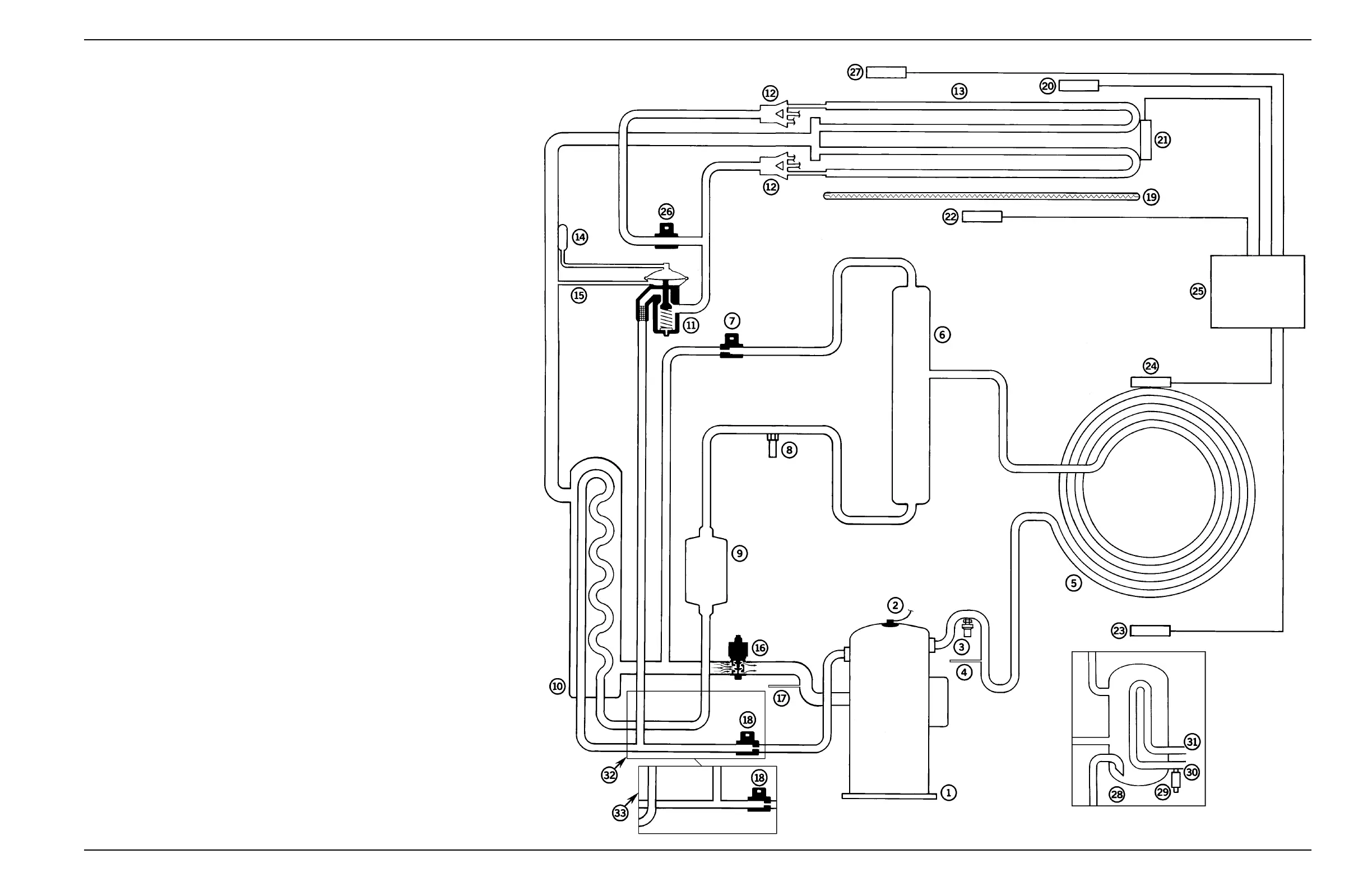
Refrigeration System Components
1. Scroll Compressor
2. Compressor Discharge Temperature Sensor (CDTS)
3. High Pressure Cutout Switch (HPCO)
4. Discharge Line Process Tube
5. Condenser Coil (Circular)
6. Receiver Tank
7. Warm Gas Bypass Valve
8. High Pressure Relief Valve
9. Filter Drier/In-line Filter
10. Heat Exchanger
11. Expansion Valve (TXV)
12. Distributors
13. Evaporator Coil
14. Expansion Valve Feeler Bulb
15. Equalizer Line
16. Modulation Valve (MV)
17. Suction Line Process Tube
18. Liquid Injection Valve (LIV) with Restrictor
19. Electric Heaters
20. Return Air Sensor (RET)
21. Evaporator Coil Sensor (ECOIL)
22. Supply Air Sensor (SUP)
23. Ambient Sensor (AMBT)
24. Condenser Coil Sensor (CCOIL)
25. Controller (µP-D)
26. Dehumidify Solenoid Valve (DSV) (Option)
27. Humidity Sensor (rH) (Option)
28. Water-Cooled Condenser-Receiver Tank (Option)
29. Water Pressure Switch (WPS) (Option)
30. Water Inlet Coupling (Option)
31. Water Outlet Coupling (Option)
32. Units Built After 7/99: Liquid Line and Liquid Injection Valve Piping
33. Units Built Before 7/99: Liquid Line and Liquid Injection Valve Piping
 Loading...