Home
Thermo King
Heat Pump
CSR-40 Series
Thermo King CSR-40 Series User Manual
5
of 1
of 1 rating
199 pages
Give review
Manual
Specs
To Next Page
To Next Page
To Previous Page
To Previous Page
Loading...
2-10
Unit Illustrations
Unit Description
CSR-20 & CSR-40, September 1999
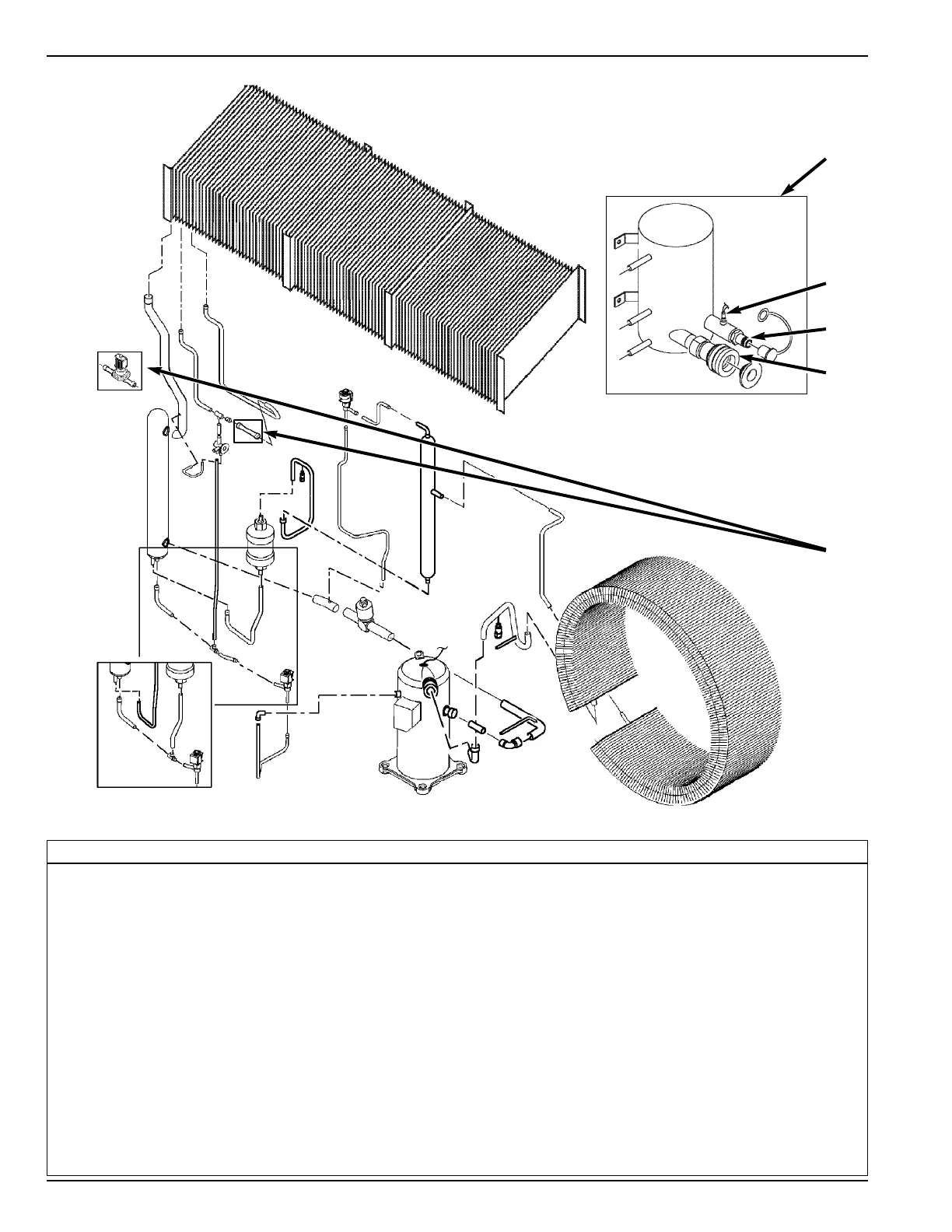
Hermetic Refrigeration System Options
1.
Water-Cooled Condenser-Receiver Tank Option
1a. Water Pressure Switch (Option)
1b. Water Inlet Coupling (Option)
1c. Water Outlet Coupling (Option)
2.
Dehumidify Valve Option (Replaces Standard Tube)
1
1a
1b
1c
2
36
38
Table of Contents
Default Chapter
5
Table of Contents
5
Introduction
9
About this Manual
9
Other Reference Manuals
9
CSR Model Features VI to
10
Safety Precautions
13
General Practices
13
Refrigerant
13
Refrigerant Oil
14
Electrical
14
Microprocessor Controller
15
Unit Decals
16
Serial Number Locations
16
Service Guide
17
Specifications
18
System Net Cooling Capacity - Full Cool
18
CSR-20SL Models with Three Evaporator Fans - Air Cooled Condensing
18
CSR-40SL Models with Three Evaporator Fans - Air Cooled Condensing
18
CSR-40 Models with Three Evaporator Fans - Air Cooled Condensing
18
CSR-40 Models with Two Evaporator Fans - Air Cooled Condensing
19
Models with Three Evaporator Fans - Water Cooled Condensing Option with 37.8 C (100 F) Water Temperature
19
Models with Three Evaporator Fans - Water Cooled Condensing Option with 30 C (86 F) Water Temperature
19
System Net Heating Capacity
19
Evaporator Airflow
20
CSR-20SL Models with Three Evaporator Fans
20
CSR-40SL Models with Three Evaporator Fans
20
CSR-40 Models with Three Evaporator Fans
20
CSR-40 Models with Two Evaporator Fans
20
Refrigeration System
21
Electrical System
22
Thermoguard
23
Dehumidify and Humidify Systems (Options)
25
Physical Specifications
25
Metric Hardware Torque Charts
27
Unit Description
28
General Description
28
Operating Modes
30
Unit Illustrations
32
Typical Unit Front View
32
Unit Options Front View
33
Evaporator Section for Models with Three Evaporator Fans - Front View
34
Evaporator Section for Models with Two Evaporator Fans - Front View
35
Standard Hermetic Refrigeration System
36
Hermetic Refrigeration System Options
37
Control Box - Door Open
38
Sabroe Remote Monitor Modem Option for Power Line Communications
39
Thermo King Modem (Integrated Remote Monitor Unit) Option for Power Line Communications
40
Integrated Remote Monitor Unit (IRMU) Option for CSR-40-116
41
Auxiliary Battery and Battery Charger Option
42
Dual Voltage Option
43
Humidity System Option
44
TRANSFRESH System Options
45
Typical Unit Back View
46
II
47
Operating Instructions
47
Unit Controls
47
Unit Instruments
48
Unit Protection Devices
48
Pretrip Inspection
49
Loading Procedure
52
Post Load Procedure
52
Post Trip Procedure
52
Μ Μ P-D Controller
53
General Description
54
Controller Display Menus
55
Software Version Display
55
Active Option Displays
55
Pause Mode Displays
56
View Menu
56
Pretrip Menu
56
Test Menu
56
Guarded Access Menu
56
Program Menu
56
Menu Display Definitions
56
Status Indicator Leds and Alarm Codes
58
Pause Alarms
59
Data Logging and Downloading Data
60
General Theory of Operation
60
Chill Loads
60
Frozen Loads
61
Automatic Phase Selection
61
Compressor Liquid Injection
61
Modulation Valve Setting (PCVAL)
61
Evaporator Fan Control
61
Condenser Fan Control
61
Sensor Check
62
Power Limit
62
Economy Mode Operation
63
Sequence of Operation
63
Unit Start-Up
63
Operating Mode Function Chart - Standard Operation
64
Operating Mode Function Chart - Optional Feature Operation
65
Continuous Temperature Control Operation
65
Defrost
68
Reviewing Software Version and Configuration
69
Displaying Alternate Fahrenheit (F) or Celsius (C) Temperatures
69
Displaying Alternate Controlling (Supply or Return) Air Sensor Temperatures
70
Initiating a Manual Defrost
71
Initiating a Full Pretrip
71
Entering a Start of Trip Marker
72
Displaying and Clearing Alarm Codes
72
Controller Menu Operating Instructions
73
Menu View Functions
73
Navigating the Menu View Screens
73
GRADE Submenu
74
LOG Submenu
74
Menu Pretrip Functions
77
Performing an Extended, Full or Single Pretrip Test from the Pretrip Menu
78
Menu Test Functions
79
Menu Guard Functions
81
Navigating Menu Guard Screens
81
Setting the Unit Configuration and Customer Configuration Numbers
82
Setting the Container Identification Number
82
Setting the Unit Serial Number
83
Setting the Time and Date
83
Setting the Compressor and on Time Hourmeters
84
Setting the User Hourmeter Types, User Hourmeter Thresholds and User Hourmeters
84
Setting the Sensor Grades
85
Changing the Display Units (C/F)
87
Menu Program Functions
88
USDA Sensors
88
PULP Sensor (Option)
89
Economy Mode
90
Dehumidify Mode (Option)
91
Humidify Mode (Option)
91
Bulb Mode (Option)
92
Power Reduction Mode
93
Controller Emergency Bypass Procedure
94
Output Module
95
Thermo Bus Tap
95
Power Module
95
Replacing the Μp-D Controller
96
Temperature Sensors
96
Diagnosis and Repair
97
Alarm Codes, Descriptions and Corrective Actions 4-46 to
98
Electrical Maintenance
119
Unit Wiring
119
Auxiliary Battery and Battery Charger (Option)
119
High Pressure Cutout Switch
119
Condenser Fan and Evaporator Fan Rotation
120
Electric Heaters
120
Integrated Remote Monitor Unit (IRMU) (Option)
121
Refrigeration System Diagnosis and Service
125
Hermetic Refrigeration System Diagnosis Procedures
125
Hermetic Refrigeration System Visual Inspection and Diagnosis Chart
127
Hermetic Refrigeration System Service Procedures
128
Service Tools
128
Refrigerant Charge
129
Compressor Oil Charge
129
Installing and Removing Piercing Type Service Valves and a Gauge Manifold Set
130
Gauge Manifold Valve Positions
131
Refrigerant Leak Test Procedure
132
Using Pressurized Nitrogen
133
Refrigerant Recovery from Hermetic Refrigeration Systems
134
Evacuation and Cleanup of the Refrigeration System
135
Charging the System with Refrigerant
139
Compressor Replacement
139
Compressor Discharge Temperature Sensor Replacement
140
Modulation Valve Repair or Replacement
141
Condenser Coil Replacement
143
Filter Drier/In-Line Filter Replacement
144
Expansion Valve Replacement
144
Heat Exchanger Replacement
145
Receiver Tank Replacement
145
High Pressure Cutout Switch Replacement
146
Warm Gas Bypass Solenoid Valve, Liquid Injection Valve or Dehumidify Valve (Option) Replacement
146
Structural/Accessory Maintenance
147
Mounting Bolts
147
Unit Inspection
147
Condenser Coil
147
Evaporator Coil
147
Defrost Drains
148
Evaporator Fan Location
148
Condenser Fan Location
148
Fresh Air Exchange System
148
Partlow (Model SR) Recording Thermometer (Option)
149
Recording Chart Replacement
149
Marking System Calibration
149
Element Replacement
150
Saginomiya (Model SKM) Recording Thermometer (Option)
150
Battery
150
Recording Chart Replacement
151
Marking System Calibration
151
Power Element Assembly Replacement
152
Timer
152
Battery Voltage Indicator
152
Humidity System (Option)
153
Pretrip Inspection
153
Inspection and Cleaning
153
Mechanical Diagnosis
154
Electrical, Refrigeration and Μ Μ P-D Menu Flow Diagrams
159
460/380 Vac Power Supply to Unit
159
230/190 Vac Power Supply to Unit
160
External 12 VDC Battery Power Supply
161
Microprocessor Awakened from Sleep Mode
162
VDC Control Circuit, Sensor Circuits, Modulation Valve Circuit and Water Pressure Circuit (Option)
163
Vac Control Circuit
164
Setpoint Enable Battery and Battery Charger Circuit (Option)
165
Remote Monitor Receptacle (4-Pin) for Bridge Lights Circuit (Option)
166
TRANSFRESH Atmosphere Control System Circuit (Option)
167
Integrated Remote Monitor System Circuit (Option)
168
Cool Mode - Chill Load
170
Cool Mode - Chill Load
173
Setpoint
173
Modulation Mode - Chill Load
175
Modulation Mode - Chill Load
176
Temperature In-Range
178
Null Mode - Chill Load (Setpoint at -9.9 C [14.1 F] or Above) Condenser Fan ON; Economy Mode off
180
Heat Mode - Chill Load (Setpoint at -9.9 C [14.1 F] or Above); Economy Mode OFF; Temperature In-Range
181
Cool Mode - Frozen Load
182
Cool Mode - Frozen Load
183
Null Mode - Frozen Load (Setpoint at -10.0 C [14.0 F] or Below) Condenser Fan OFF; Economy Mode off
184
Null Mode - Frozen Load (Setpoint at -10.0 C [14.0 F] or Below) Condenser Fan OFF; Economy Mode on
185
Defrost
186
CSR-40 Wiring Schematic for All Models with Three Evaporator Fans
187
CSR-40 Wiring Schematic for All Models with Two Evaporator Fans
191
Refrigeration System Components
195
5
Based on 1 rating
Ask a question
Give review
Questions and Answers:
Need help?
Do you have a question about the Thermo King CSR-40 Series and is the answer not in the manual?
Ask a question
Thermo King CSR-40 Series Specifications
General
Brand
Thermo King
Model
CSR-40 Series
Category
Heat Pump
Language
English
Related product manuals
Thermo King CSR-40SL-126
199 pages
Thermo King CSR-20 Series
199 pages
Thermo King CRR-20
200 pages
Thermo King CRR-40
200 pages
Thermo King Ce-Series
274 pages
Thermo King CRR-40 800
170 pages
 Loading...