INSTALLATION
110
NA10 - Manual - 04 - 2022
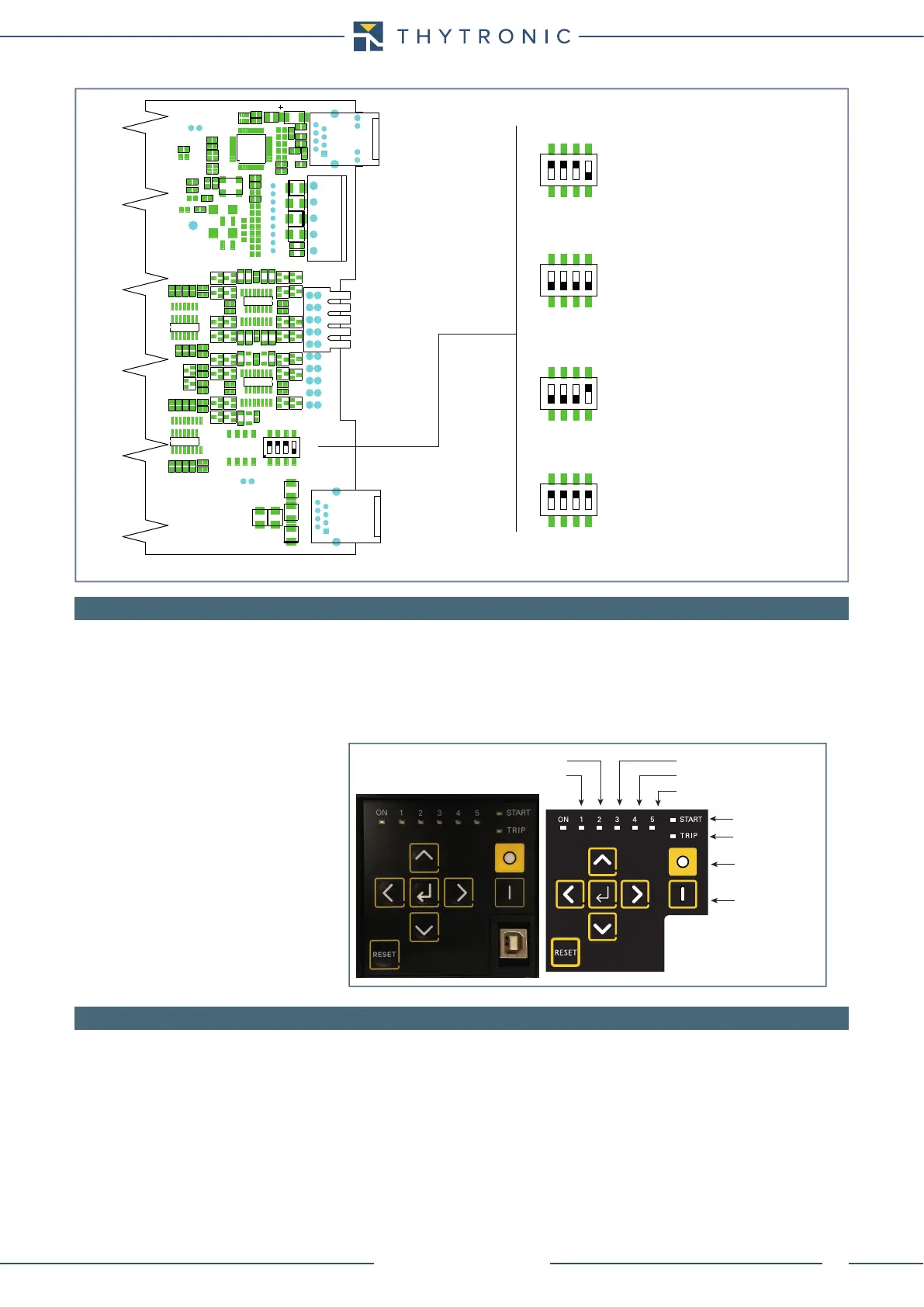
6.5 LED ALLOCATION
Following indicator LEDs are available on the front panel:
• LED ON (green): if no diagnostic anomalies are detected, the green LED is turned ON while any fault
is highlighted by flashing.
• LEDs 1...5 (red) are freely assignable from the user to any protective and/or control functions.
• LED START (yellow) committed for start information of any protective functions.
• LED TRIP (red) committed for trip information of any protective functions.
6.6 FINAL OPERATIONS
Before energizing the electric board, it is advisable to check that:
• The auxiliary voltage in the panel falls within the operative range of Pro_N relays.
• The rated current (1 A or 5 A) of the line CT’s corresponds to the setting of Pro_N relays.
• All wirings are correct.
• All screws are tightly screwed.
set-In.ai
Dip-switch localization concerning the nominal current setting inside the CPU board
Default settings:
- I
n
=5 A
- I
En
=1 A
Settings:
- I
n
=5 A
- I
En
=5 A
Settings:
- I
n
=1 A
- I
En
=1 A
Settings:
- I
n
=1 A
- I
En
=5 A
ETHERNET
THYBUS
485
1 A
5 A
S5
1 2 3 4
IL1
IL2
IL3
IE
1 A
5 A
S5
1 2 3 4
IL1
IL2
IL3
IE
1 A
5 A
S5
1 2 3 4
IL1
IL2
IL3
IE
1 A
5 A
S5
1 2 3 4
IL1
IL2
IL3
IE
1 A
5 A
S5
1 2 3 4
IL1
IL2
IL3
IE
Start
79
CB CLOSED (52b)
CB OPEN (52a)
50-51 (I>, I>>, I>>>)
50N-51N (IE>, IE>>)
Trip
CB Open
CB Close
 Loading...


