FUNCTION CHARACTERISTICS
78
NA10 - Manual - 04 - 2022
CT supervision - 74CT
Preface
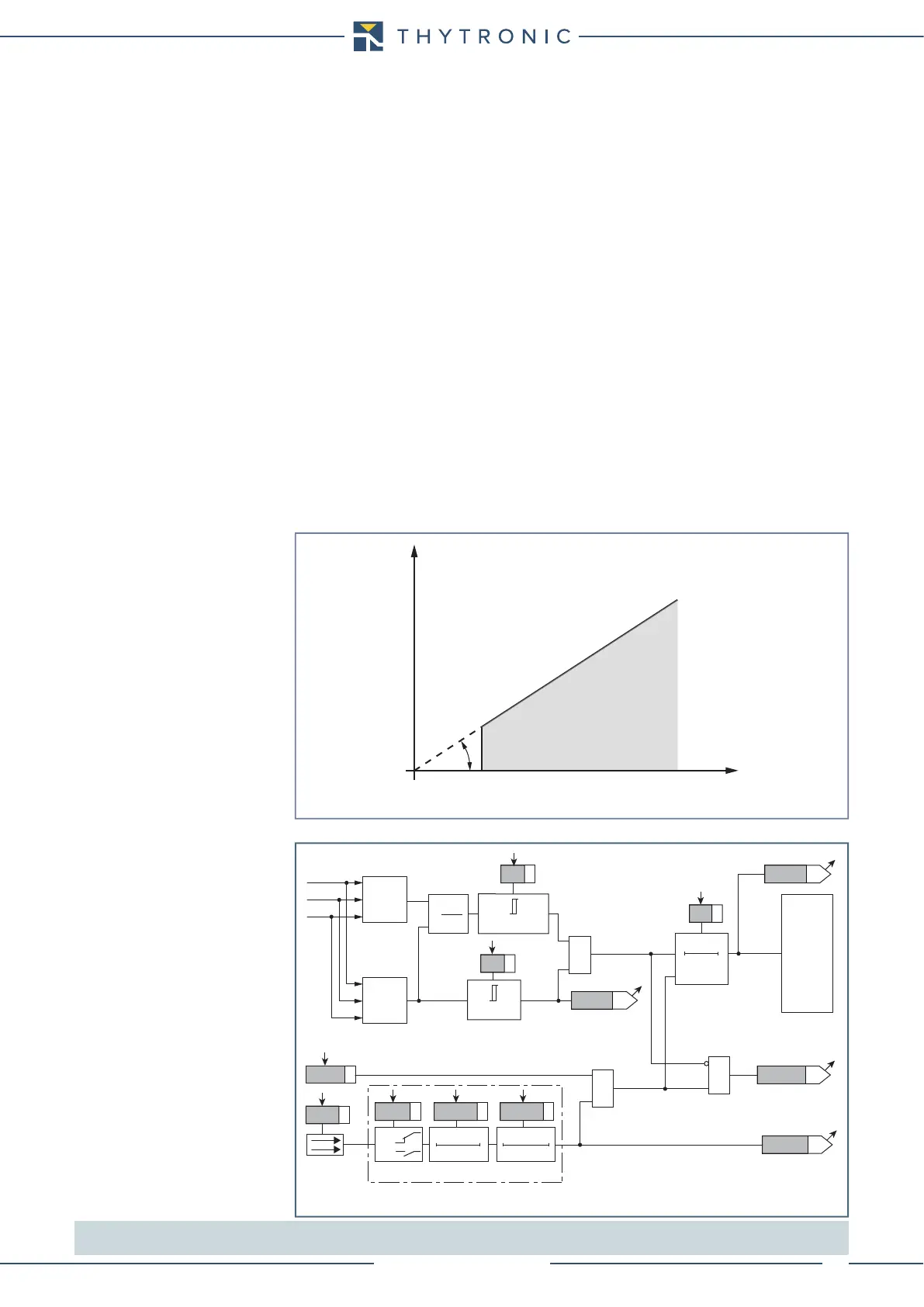
The CT monitoring function is employed to issue an alarm when secondary phase CTs and/or phase
input failures are detected.
Interruptions are detected by means of a symmetry criterion of the I
L1
, I
L2
, I
L3
input currents.
The symmetry factor is calculated comparing the minimum and maximum of the fundamental compo-
nents of the three phase currents (I
LMIN
/ I
LMAX
).
Operation and settings
The starting of the timer occurs if both the following conditions are filled:
A) (I
LMIN
/ I
LMAX
) < S
<
that is the symmetry factor is lower than the S
<
adjustable threshold;
B) I
LMAX
> I*
Where
I*: maximum phase current threshold
S<: element pickup value
If both conditions are filled over the t
S<
adjustable time an alarm is issued
The output may be assigned to the selected S<TR-K output relays inside the Set \ CT supervi-
sion-74CT submenu; the same for addressing the LED indicators S<TR-L.
If the S<-BLK1 parameter is set to ON, and a binary input is designed for logical block (Block1), the
CT supervision function is blocked off whenever the given input is active. The trip timer is held in re-
set condition, so the operate time counting starts when the input block goes down.
[1]
The S<-BLK1
parameter is available inside the Set \ CT supervision-74CT menu.
The element may be enabled or disabled by setting ON the 74CT Enable parameter available
inside the Set \ CT supervision-74CT menu.
All the parameters are common for A and B Profiles.
Note 1 The exhaustive treatment of the logic block (Block 1) function may be found in the “Logic Block” paragraph inside CONTROL AND MONITORING
section
char74CT.ai
I*
α
I
LMIN
I
LMAX
tgα=S<
Current asimmetry monitoring - 74CT
TRIP
NO TRIP
CT monitoring logic diagram - 74CT
Fun-74CT.ai
&
0
T
t
s
<
t
S<
I
LMIN
/I
LMAX
<
S<
S<
TRIPPING MATRIX
(LED+RELAYS)
Trip S<
Start I*
BLK1 S<
I
LMAX
>I*
I*
Enable (ON≡ Enable)
Block1 input (ON≡ Block)
&
&
S<BLK1
Block1
Block1
Binary input INx
T 0
Logic
INx
t
ON
INx
t
ON
INx
t
OFF
T0
n.o.
n.c.
INx
t
OFF
I
L1
I
LMAX
I
L2
I
L3
I
LMIN
I
LMIN
I
LMAX
S<TR-K
S<TR-L
RESET
 Loading...


