FUNCTION CHARACTERISTICS
74
NA10 - Manual - 04 - 2022
Remote tripping
Preface
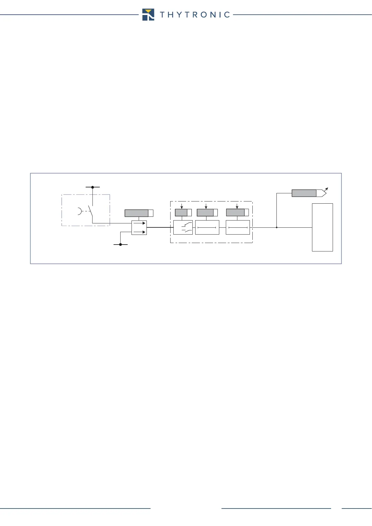
Some output relays may be programmed for remote trip function resulting from a command coming
from a binary input.
If a binary input is designed for remote trip acquisition, an output relay allocated to the same function
is triggered when the input (IN1 and/or INx) is active.
Operation and settings
The Remote trip matching must be assigned to the selected binary inputs inside the Set \ Inputs \
Binary input IN1...INx menus.
When a binary input is programmed for remote trip acquisition, the IN1 tON, INx tON, IN1 tOFF
and INx tOFF time delays must be reset to zero; the Logic parameters (ON/OFF) must be pro-
grammed in the same way of the related circuit connected with-it.
The RemTrip-K matching must be assigned to the selected output relays inside the
Set \ Remote tripping submenu; the same for addressing the LED indicators (RemTrip-L).
When output relays are programmed for remote tripping, the t
TR
time delays must reset to zero;
the operation mode must be set with self reset (No-latched inside Set \ Relays submenu) and the
Logic parameters (Energized/De-energized) must be programmed in the same way of the related
binary input connected with-it.
All the parameters are common for A and B Profiles.
Fun-Remote-trip.ai
Remote trip
+UAUX
-UAUX
Remote trip
Binary input INx
RemTrip-K
RemTrip-L
T 0
INx
t
ON
T0
n.o.
n.c.
INx tON
Logic
INx tOFF
INx
t
OFF
TRIPPING MATRIX
(LED+RELAYS)
Remote trip
Remote trip logic diagram
 Loading...


