FUNCTION CHARACTERISTICS
87
NA10 - Manual - 04 - 2022
Demand measures
Demand measures are calculated as:
Fixed demand
Fixed demand I
L1FIX
,
I
L2FIX
,
I
L3FIX
Every fixed demand period t
FIX
an average magnitude is calculated based on samples taken every 1
second. Update is carried out at the end of the same period. The fixed demand measures may be reset
to zero by means the Reset on demand measures command (ThyVisor Commands menu).
The tFIX parameter (Fixed demand period) is available inside the Set\Demand measures menu.
Rolling demand
Rolling demand I
L1ROL
,
I
L2ROL
,
I
L3ROL
The average magnitude is calculated inside a mobile window of N·T length where:
• N is the user-defined number of cycles and,
• T is the user-defined sub-period.
An average magnitude is calculated based on samples taken every 1 second; update is carried out
at the end of the every sub-period. The rolling demand measures may be reset to zero by means the
Reset on demand measures command (ThyVisor Commands menu).
The tROL (Rolling demand period) and N.Rol (Number of cycles for rolling on demand) parameters are
available inside the Set\Demand measures menu.
Peak demand
Peak demand I
L1MAX
,
I
L2MAX
,
I
L3MAX
Every sub-period t
ROL
the maximum value of the average magnitude is calculated based on samples
taken every 1 second. Update is carried out at the end of the same period. The peak demand measures
may be reset to zero by means the Reset on demand measures command (ThyVisor Commands menu).
The tROL (Rolling demand period) parameter is the same for rolling demand setting.
Minimum demand
Minimum demand I
L1MIN
,
I
L2MIN
,
I
L3MIN
Every sub-period t
ROL
the minimum value of the average magnitude is calculated based on samples
taken every 1 second. Update is carried out at the end of the same period. The peak demand measures
may be reset to zero by means the Reset on demand measures command (ThyVisor Commands menu).
The tROL (Rolling demand period) parameter is the same for rolling demand setting.
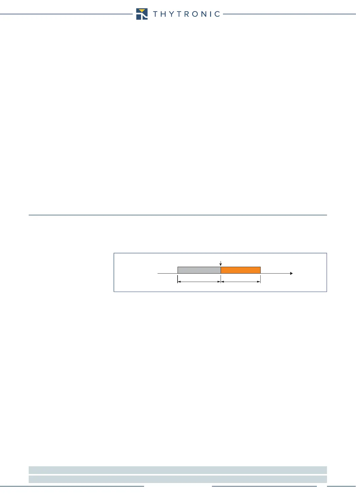
Oscillography
Trigger Setup
Following parameters, available inside the Set\Oscillography\Trigger Setup menu, are user-program-
mable:
• Pre-trigger time and Post-trigger time.
• Element pickup trigger; the information recording starts when a state transition on any protec-
tive element occurs if the parameter is set to ON.
• Trigger from outputs; the information recording starts when a state transition on the selected
output relay occurs if the parameter is set (K1...K6).
• Binary input trigger; the information recording starts when a state transition on the selected
binary input occurs if the parameter is set to ON.
• Trigger from inputs; the information recording starts when a state transition on the selected
binary input occurs if the parameter is set (IN1...IN2).
• 80% Buer alarm; when the 80% of the buffer space is reached an alarm may be issued if the
parameter is set to ON.
Set sampled channels
The desired sampled quantities may be select inside the Set \ Oscillography \ Set sampled channels
menu (i
L1
, i
L2
, i
L3
, i
E
).
Set analog channels
The desired sampled quantities may be select inside the Set \ Oscillography \ Set analog channels
menu.
Everyone of twelve analog channel may be associated to one of the selected measures (Frequency,
I
L1
, I
L2
, I
L3
, I
E
, I
L1-2nd
, I
L2-2nd
, I
L3-2nd
, I
-2nd/
I
L
, T1...T8
[1]
).
Set digital channels
The desired digital quantities may be select inside the Set \ Oscillography \Set digital channels menu.
Everyone of twelve digital channel may be associated to one of the selected I/O signal (K1... K6, K7...
K10, IN1, IN2, IN3...IN42
[2]
).
Note 1 The temperature measure is acquired by means of Pt100 probes (eight inputs on MPT module)
Note 2 The output relay K7...K10 and binary input INx...IN42 states is meaningful when the I/O circuits are present (MRI and MID16 modules)
trigger.ai
Oscillography
Trigger
Time
pre-trigger post-trigger
 Loading...


