13
4. The display ‘GE24’ starts to blink.
5. When the display stops blinking, the
setting is modied.
To change from GEL to Lead-Acid,
repeat the procedure pressing button
(2) instead of button (3).
ATTENTION:
As the machine is a 24V model, do not
set the batteries at 36V.
HOUR METER
The machine is equipped with an hour
meter located on the same display (1)
of the battery charge level indicator.
Keeping the button (2) pressed, the
rst data indicates the working hours
and after a few seconds the working
minutes are shown.
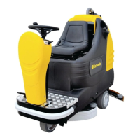
SQUEEGEE ASSEMBLY
1. Hold the squeegee support (1) lifted
from the oor.
2. Insert the threaded parts of the two
knobs (4) making them slide inside
the two slots on the support placed on
the upper part of the squeegee (2).
3. Put the washers (3) into position,
there are two for each knob, so that
they are assembled one under and
the other on top of the two slots on the
support.
4. Secure the squeegee by rotating
the two knobs (4) clockwise.
5. Insert the squeegee hose (5) into
its coupling, as indicated in the gure.
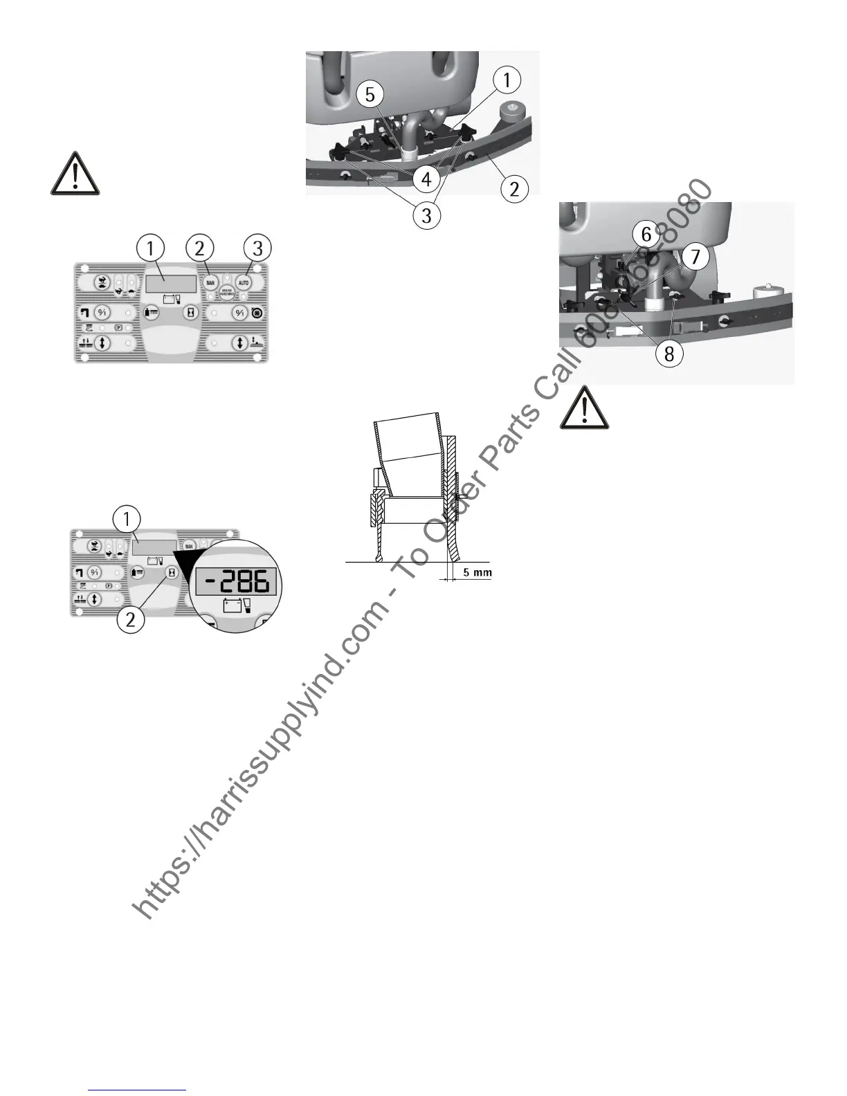
ADJUSTMENT OF THE SQUEEGEE
In order to have a perfect drying
result through the squeegee, the rear
rubber must have the lower bending
uniformly adjusted in all its length. For
the adjustment, it is necessary to put
the machine in working condition and
the vacuum motor has to be switched
on and the brushes have to function
together with the detergent solution.
The lower part of the rubber is too
much bent
Take off the pressure rotating the wing
nut (6) counterclockwise.
The lower part of the rubber is not
much bent
Increase the pressure rotating the
wing nut (6) clockwise. Check that
the wheels which adjust the height
do not rest on the oor, in this case
adjust them as indicated in paragraph
"Height adjustment".
The bending is not uniform
Adjust the squeegee inclination rotat-
ing counterclockwise the wing nut (7)
to increase the bending in the central
part, or clockwise to increase the
bending on the extremities.
Height adjustment
Once that the pressure and inclination
of the squeegee have been adjusted,
it is necessary to x this optimum con-
dition making touch slightly the wheels
onto the oor. Rotate the registers
(8): clockwise to lower the wheels or
counterclockwise to raise them. Both
wheels must be adjusted in the same
measure.
ATTENTION:
Every type of oor requires a specic
adjustment. For example, concrete
oors (where the friction results to
be high) need little pressure, while
smooth oors (ceramics) need higher
pressure.
If the cleaning operations are made
always on the same type of oor, the
adjustment can change only in func-
tion of the rubber wear.
SPLASH GUARD ASSEMBLY
The two splash guards have to be as-
sembled onto the brushes base group
as indicated in the following gures.
Insert the metal strips inside the
suitable slots present on the rubber.
Place the round hole at the extrem-
ity of the strip onto the pin (1) placed
in the front part of the brushes base
group. Secure the strips through the
nut blocking it.
Block the coupling lever (2) in the
rear part of the brushes base group
to the ring placed at the extremity of
the metal strip still free. Please act as
above for both splash guard rubbers.
With the brushes assembled, the
splash guard must slightly touch the
oor.
For the disassembly it is necessary
to proceed inversely with above-men-
tioned operations.
https://harrissupplyind.com - To Order Parts Call 608-268-8080
 Loading...