–11–
Hydro Unit
Installation Manual
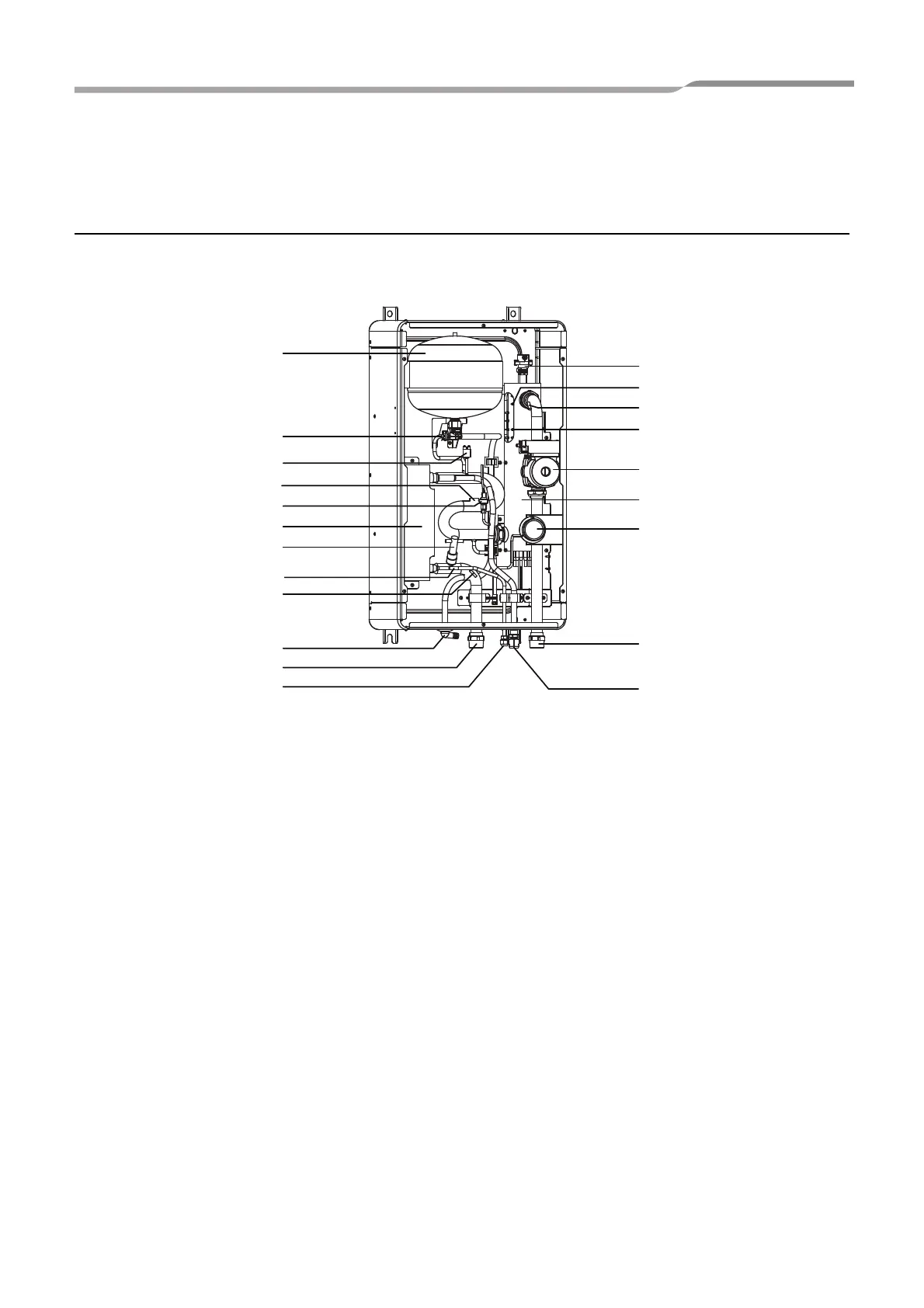
6 Main components of Hydro Unit
Exploded view and description for Hydro Unit
▼ Fig. 6-01
1 : Expansion vessel
2 : Temperature sensor (for Heat pump outlet -TWO)
3 : Pressure sensor
4 : Heat exchanger
5 : Flow switch (10 L/min (4.5 kW), 13 L/min (8 kW), 18 L/min (14 kW))
6 : Temperature sensor (for refrigerant -TC)
7 : Temperature sensor (for water inlet -TWI)
8 : Drain nipple
9 : Water inlet connection
10 : Refrigerant liquid connection
11 : Air relief valve
12 : Overpressure preventive valve (0.43 MPa (4.3 bar))
13 : Thermal protector (auto)
14 : Temperature sensor (for water outlet THO)
15 : Thermal protector (Single operation)
16 : Water pump
17 : Backup heater (3 kW, 3 kW x 2, 3 kW x 3)
18 : Manometer
19 : Water outlet connection
20 : Refrigerant gas connection
21 : Pressure switch (4.15 MPa)
5
10
12
8
9
6
7
3
2
1
21
19
20
14
16
18
17
15
13
11
4
11-EN
 Loading...