–32–
Hydro Unit
Installation Manual
EN
9 Start up and configuration
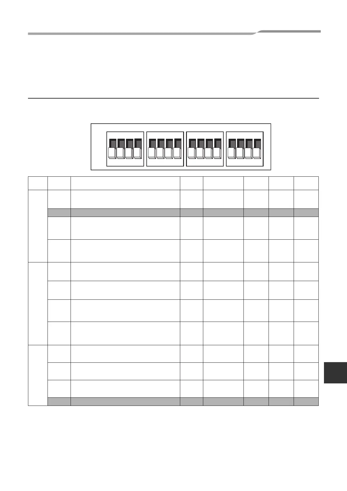
Set the DIP switches and function codes.
Setting DIP switches on the board in the Hydro Unit
• Detach the front cover and the electrical control box cover of the Hydro Unit.
• Set the DIP switches on the main board.
SW No. DIP No. Description Default
After
Commissioning
Change 1 Change 2 Change 3
02
1
Boiler install location
OFF = Heating side after 3 way valve
ON = Before 3 way valve
OFF
2 Not Used – – – – –
3
Used to when an external cylinder thermostat is
connected
OFF = No external cylinder thermostat;
ON = External tank thermostat connected
OFF
4
Used to when an external room thermostat is
connected
OFF = No external room thermostat;
ON = External room thermostat connected
OFF
10
1
P1 Pump operation for hot water
OFF = synchronised with heat pump
ON = Normally run
OFF
2
P1 Pump operation for heating
OFF = Normally run
ON = Stopped at the outside temperature over 20 °C
OFF
3
Synchronisation of Pump P2.
OFF = P1 synchronised with pump P1
ON = P2 continuous operation (pump off when
remote controller switched off)
OFF
4
Pump P1 power of regular, When long-term thermo-
off.
OFF = None operation
ON = regular power
OFF
11
1
Used to activate Hydro Unit back up heaters.
OFF = Back up heaters activated;
ON = back up heaters de-activated
OFF
2
Used to activate hot water cylinder electrical heater.
OFF = hot water cylinder heater activated;
ON = hot water cylinder heater de-activated
OFF
3
Used to activate external booster heater output.
OFF = external booster heater output activated;
ON = external booster heater output de-activated
OFF
4 Not Used – – – – –
ON
OFF
SW10 SW11 SW12 SW13
1
2
3
4
ON
1
2
3
4
ON
1
2
3
4
ON
1
2
3
4
ON
32-EN
 Loading...