11-1-3. Refrigerant recovery procedure B (Case of outdoor unit
backup operation setting)
<Outline>
If outdoor unit backup operation setting is performed, use an alternative refrigerant recovery procedure as
described below, provided that the power cannot be turned on for the failed outdoor unit. (Refrigerant will be
recovered from the failed outdoor unit using the test cooling operation function.)
Note 1: If cooling-season outdoor unit backup operation or outdoor unit backup operation is in progress with the
power supply to the failed outdoor unit turned on, follow the procedure described in “11-1-2. Refrigerant
recovery procedure A (Case of no outdoor unit backup operation setting)”. If outdoor unit backup
operation setting is performed with the power supply to the failed outdoor unit turned on, recovery
operation can only start
after putting the outdoor-outdoor communication connector on the interface P.C.
board of that unit [CN03] back to its initial state and resetting the power supply.
Note 2: If the power cannot be turned on the failed outdoor unit, the solenoid valves and PMVs of the unit cannot
be turned on, so that it reduces the amount of recovered refrigerant compared to a standard pump-down
operation. Recover the residual gas in the unit using a refrigerant recovery device, and be sure to
measure the amount of recovered refrigerant.
<Work procedure>
[Setup of failed outdoor unit]
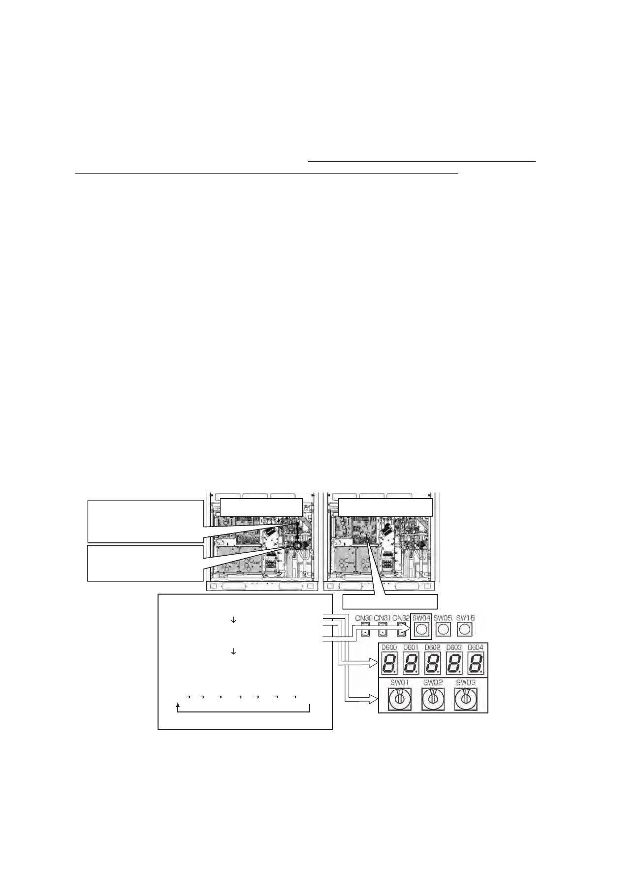
(1) Connect the liquid pipe check joint and the low pressure-side check joint using a gauge manifold, and purge the
manifold of air (to recover refrigerant from the liquid tank and heat exchangers).
(2) Fully close the liquid pipe packed valve of the failed outdoor unit.
(Leave the service valve of the gas pipe and the packed valve of the balance pipe fully open.)
[Setup of unit selected as header unit (hereafter “header outdoor unit”)]
(3) Set SW01/02/03 on the interface P.C. board of the header outdoor unit to 2/5/1. After [C. ] [… … …] is displayed
on the 7-segment display, press SW04 and hold for 5 seconds or more.
(4) After [C. …] [… –
C] is displayed on the 7-segment display, the system starts operating in the test cooling
operation mode.
(5) Set SW01/02/03 on the interface P.C. board of the header outdoor unit to 1/2/2 to have the low-pressure sensor
output (psi) displayed on the 7-segment display.
(6) Approx. 10 minutes after the system starts up, fully close the gas pipe service valve of the failed outdoor unit.
[Selection of outdoor unit for pressure adjustment]
(7) Select the header unit as the unit for pressure adjustment.
(1)
(2)
Pd Ps Td1 Td2 TS1 TE1 TE2 C~C
Connect liquid pipe check joint and
low pressure-side check joint using
gauge manifold, and purge manifold
of air.
Failed outdoor unit Unit selected as header unit
Interface P.C. board
Fully close liquid pipe service valve.
(Leave gas and balance pipes fully
open.)
(3) Set SW01/02/03 to 2/5/1.
[C. ] [… … …] is displayed
(4) Press SW04 and hold for 5 seconds or more.
[C. …] [… – C] is displayed. (Test cooling
operation begins).
(5) Set SW01/02/03 to 1/2/2 to have low-pressure
sensor output (MPa) displayed.
Press SW04 to have low-pressure
sensor output displays.
− 225 −
 Loading...