− 251 −
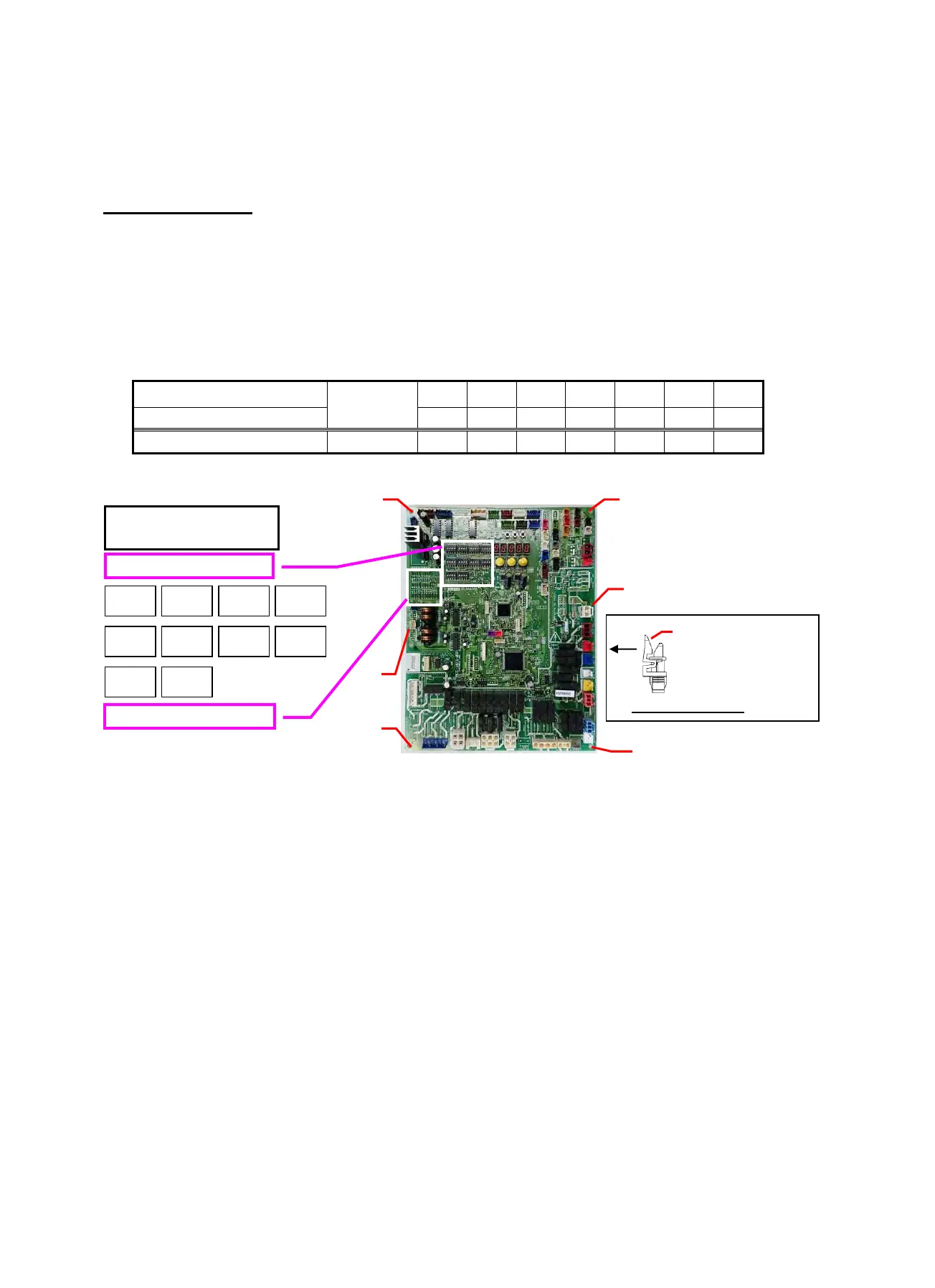
14-1-3. Interface P.C. Board (MCC-1673) Replacement Procedure
This Interface board is commonly installed in different models before shipment. When the board assembly is to
be replaced, check the displayed inspection contents below and replace the board in accordance with the
model, following the below procedure.
Replacement steps:
(1) Turn off the power supply of the outdoor unit and wait at least 5 minutes.
(2) Remove all of the connectors connected to the interface board. (Remove the connectors by pulling the
connector body. Do not pull the wire).
(3) Remove the interface board from the six PCB mounts (①).
(4) Cut the jumper wires of the service board, as instructed in the table below.
The jumper setting differs from original supplied PCB, therefore be sure to configure the Jumpers as in the
table below.
If the model is not specified, check code "L10" is displayed and the equipment will not operate.
Model name
Model size
J07 J09 J10 J11 J12 J22 J25
Service P.C. Board Yes Yes Yes Yes Yes Yes Yes
MMY-MAP0726FT2P-UL 990W Cut - Cut - -
-
Cut
(5) Set the DIP switch settings of the service board to match the switch settings of the PCB being replaced.
(6) Install the service board to the outdoor control unit (Confirm that it is securely fixed to the PCB Mounts).
(7) Connect the connectors (Confirm that they are correctly and securely inserted).
(8) If a component on the board is bent during board replacement, adjust it manually ensuring that it is not short
or contact other parts.
(9) Install the cover, then turn on the power supply. Check the operation.
Jumpers
DIP Switches
SW06 SW07
SW11 SW12
SW17
SW13 SW14
SW16
SW10 SW09
Interface P.C.Board
(43T6V995)
①
①
①
①
① PCB
Mounts
①
Push this part to the
direction of the arrow.
And remove the PCB.
PCB Mounts ①
 Loading...