7-2. Applied Control of Outdoor Unit
Optional control P.C. boards provide access to a range of functions as listed below.
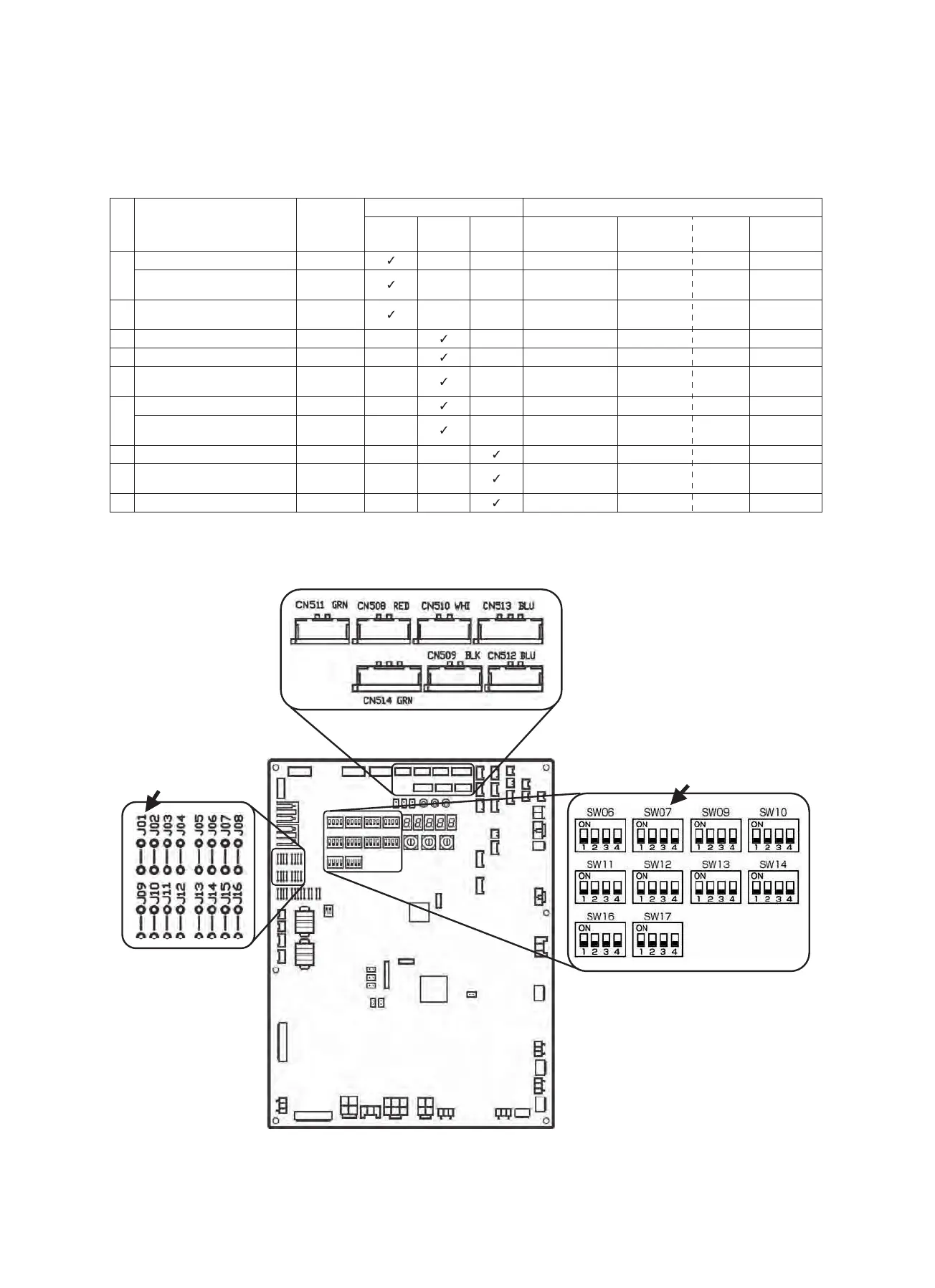
Layout of Outdoor Unit Interface P.C. Board
* DIP switch settings and jumper wire statuses vary from function to function.
No. Function
Outdoor unit
for control
P.C. board
connection
Control P.C. board to be used Outdoor unit interface P.C. board setting*
PCDM4UL PCMO4UL PCIN4UL
Connector No. DIP SW No. Bit
Jumper to be
removed
1
Power peak-cut Control (Standard) Header unit
– – CN513(blue) SW07 1 –
Power peak-cut Control (For one
input function)
Header unit
– – CN513(blue) SW07 1 J16
2
Power peak-cut Control (Enhanced
Functions)
Header unit
– – CN513(blue) SW07 1.2 –
3 Snowfall Fan Control Header unit –
– CN509(black) – – –
4 External master ON/OFF Control Header unit –
– CN512(blue) – – –
5
Night operation (sound reduction)
Control
Header unit –
– CN508(red) – – –
6
Operation Mode Selection Control Header unit –
– CN510(white) – – –
Operation Mode Selection Control
(forced choice)
Header unit –
– CN510(white) – – J01
7
Trouble/Operation output
Header unit – –
CN511(green) – – –
8 Compressor Operation Output
Individual
outdoor unit
––
CN514(green) – – –
9 Operating Rate Output Header unit – –
CN514(green) SW16 1 –
Connector layout
DIP switch layout
Interface P.C. Board
Jumper wire layout
− 68 −
 Loading...